Tweeted twitter.com/StackElectronix/status/1334603366421422090
added 290 characters in body
Source Link

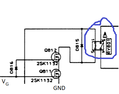
background first: I am currently trying to repair my old Pioneer amplifier (A-405R). The error description behaviour is a sporadic infinite triggering of the relay (marked blue one in the schematics). In the working case, V_G = 4.8 V. In the not working case it is below 4 V.

What I am really wondering (due to lack of HW experience): Why are these two MOSFETs (2SK1132: Datasheet MOSFET) in series? So I thought the benefit of that MOSFET is to switch the relay on and off. Why do you need to then there?

enter image description hereDetailed MOSFET schematic

EDIT: See here for the more detailed schematic. Complete datasheet of the amplifier can be found under: Datasheet Amplifier

Primary Assy / Power Supply

background first: I am currently trying to repair my old Pioneer amplifier (A-405R). The error description behaviour is a sporadic infinite triggering of the relay (marked blue one in the schematics). In the working case, V_G = 4.8 V. In the not working case it is below 4 V.

What I am really wondering (due to lack of HW experience): Why are these two MOSFETs (2SK1132: Datasheet MOSFET) in series? So I thought the benefit of that MOSFET is to switch the relay on and off. Why do you need to then there?

enter image description here

background first: I am currently trying to repair my old Pioneer amplifier (A-405R). The error description behaviour is a sporadic infinite triggering of the relay (marked blue one in the schematics). In the working case, V_G = 4.8 V. In the not working case it is below 4 V.

What I am really wondering (due to lack of HW experience): Why are these two MOSFETs (2SK1132: Datasheet MOSFET) in series? So I thought the benefit of that MOSFET is to switch the relay on and off. Why do you need to then there?

Detailed MOSFET schematic

EDIT: See here for the more detailed schematic. Complete datasheet of the amplifier can be found under: Datasheet Amplifier
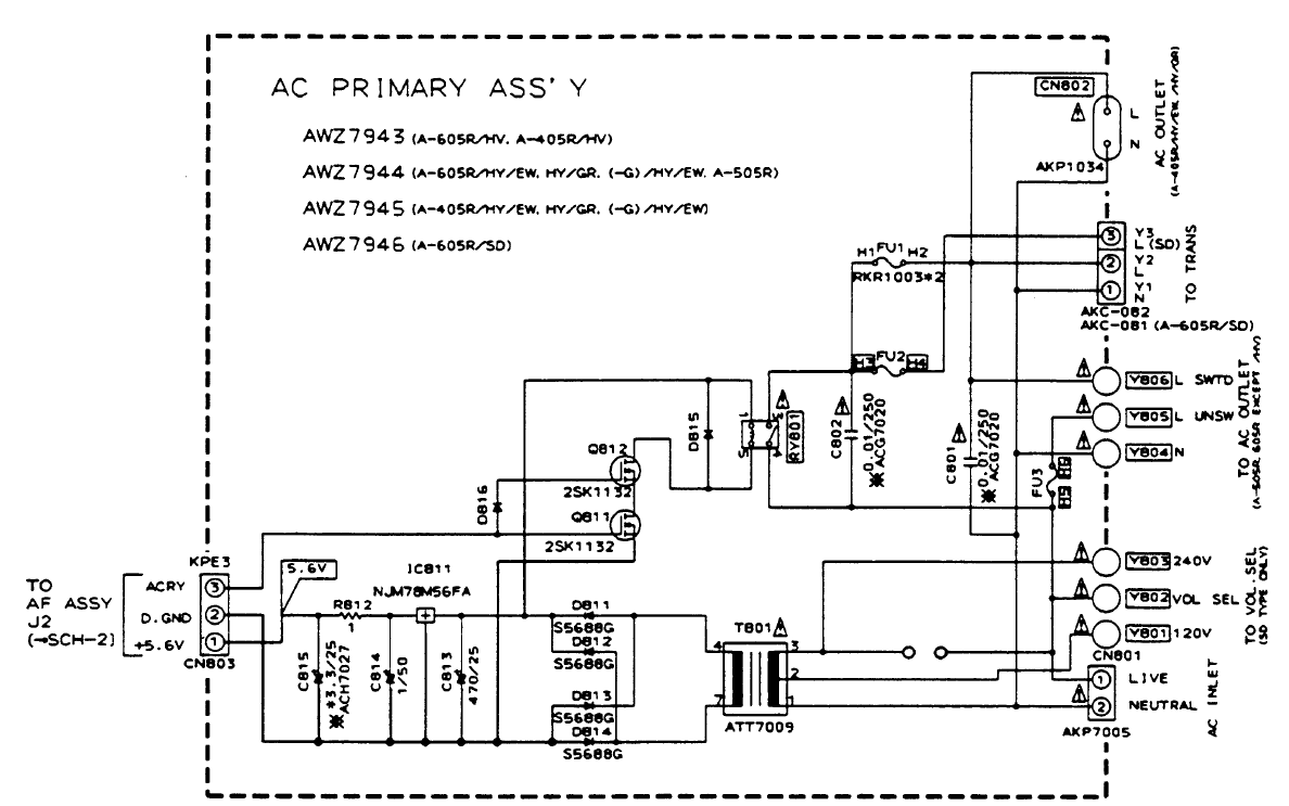
Primary Assy / Power Supply

series, not serial
Source Link
Chris Stratton
  • 33.6k
  • 3
  • 45
  • 90

What is the reason to put two MOSFETs in a serialseries connection?

background first: I am currently trying to repair my old Pioneer amplifier (A-405R). The error description behaviour is a sporadic infinite triggering of the relay (marked blue one in the schematics). In the working case, V_G = 4.8 V. In the not working case it is below 4 V.

What I am really wondering (due to lack of HW experience): Why are these two MOSFETs (2SK1132: Datasheet MOSFET) in a serial connectionseries? So I thought the benefit of that MOSFET is to switch the relay on and off. Why do you need to then there?

enter image description here

What is the reason to put two MOSFETs in a serial connection?

background first: I am currently trying to repair my old Pioneer amplifier (A-405R). The error description behaviour is a sporadic infinite triggering of the relay (marked blue one in the schematics). In the working case, V_G = 4.8 V. In the not working case it is below 4 V.

What I am really wondering (due to lack of HW experience): Why are these two MOSFETs (2SK1132: Datasheet MOSFET) in a serial connection? So I thought the benefit of that MOSFET is to switch the relay on and off. Why do you need to then there?

enter image description here

What is the reason to put two MOSFETs in a series connection?

background first: I am currently trying to repair my old Pioneer amplifier (A-405R). The error description behaviour is a sporadic infinite triggering of the relay (marked blue one in the schematics). In the working case, V_G = 4.8 V. In the not working case it is below 4 V.

What I am really wondering (due to lack of HW experience): Why are these two MOSFETs (2SK1132: Datasheet MOSFET) in series? So I thought the benefit of that MOSFET is to switch the relay on and off. Why do you need to then there?

enter image description here

Source Link

What is the reason to put two MOSFETs in a serial connection?

background first: I am currently trying to repair my old Pioneer amplifier (A-405R). The error description behaviour is a sporadic infinite triggering of the relay (marked blue one in the schematics). In the working case, V_G = 4.8 V. In the not working case it is below 4 V.

What I am really wondering (due to lack of HW experience): Why are these two MOSFETs (2SK1132: Datasheet MOSFET) in a serial connection? So I thought the benefit of that MOSFET is to switch the relay on and off. Why do you need to then there?

enter image description here