I'm trying to build simple 50Hz current transformer (just to see the mains current - maybe some microcontroller measurment in the future) following the answer to this question.
When I connect it to a 100W 240V light bulb (incandescent) the output sine wave is perfect.
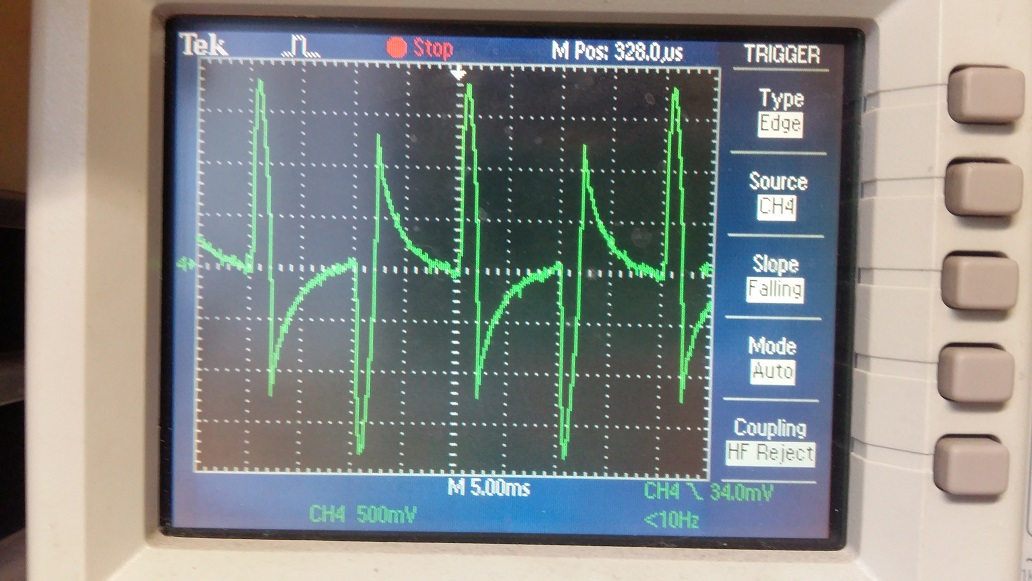
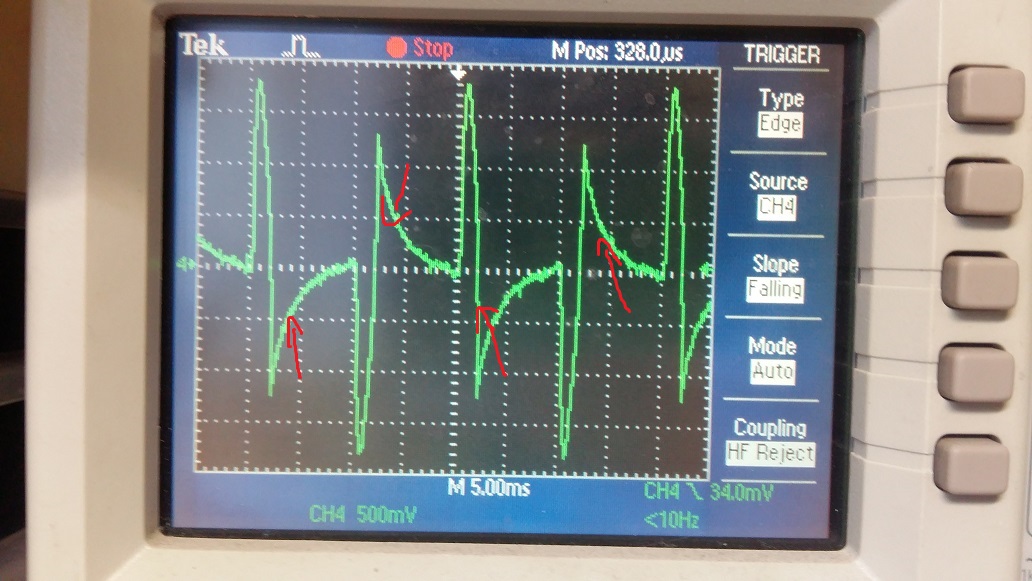
When I connect an SMPS (laptop charger) I get this strange waveform:
What is mostly strange for me is indicated with arrows. Why is that? Shouldn't be this flat after a peak?
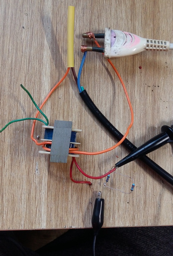
This is a photo of my setup:
This transformer is just small one (8W?) took from plugpack charger of some kind - 12V output. I'm measuring the waveform on its original primary side, loaded with 9kOhm resistor (two 18k in parrallel.)
Why is this waveform so strange? Is this transformer constuction ok? Maybe the inductances are too high/low?
EDIT
As Andy Aka suggested - I reduced the loading resistor value to 10Ohm. The waveform is now flat between peaks (as it should be), but the overall amplitude is very low - 20mV for 100W incandescent ligth bulb. Can I somehow increase the amplitude, or just add an amplifier?
What I tried to increase amplitude: I wound another 10 turns with thinner wire and connected this loading resistor there, now completly no voltage appeared on it, but according to the transformer formula, it should be quite large. Iout = Iin/Iin*(Nsec/1/Nsec). For original primary N was like 2000 or so. Why then there is no voltage across this resistor?


