deleted 37 characters in body
Source Link
KMC
  • 1.4k
  • 3
  • 22
  • 51

I'm having difficulty understandingI don't understand what Parasitic Properties: This is an active load means in LTSpice givenprovided as an option in the current source configuration window. So I plotted out the schematics, one with the active load checked and the other without, and compared their simulated traces. Without being checked as an "active load", the current source behaves just like how a current source should be - supplying a constant 2A current through \$ I_1 \$ (topupper schematic and trace). But ifIf I checkthen checked the "active load", the current through \$ I_1 \$ stays constant at 2A2A only after voltage goes above 0.5Vwhen \$ V_1 > 0.5V \$, and down to -16A whenif \$ V_1 \$ is\$ V_1 = -2V \$, the current source miraculously supplies -2V16A.!

  1. It makes no sense to me that the current source can sink 16A while I've already fixed it a DC value of \$ I_1 = \$ 2A - where is this extra 12A comes from?
  2. I don't understand how a load can be modeled as a current source. Isn't a load a component or a sub-circuit that sinks current and dissipates energy? Current source supplies energy to the circuit - how could it supply electrons to the circuit yet dissipating moreand dissipate energy at the same time (that \$ 16A*2V=32W \$!) thani.e. suppling 2A current to the rest of circuit?) but dissipates .\$ 16A*2V=32W \$ ?!

Perhaps a related question here: LTSpice active load current generator soft saturation

Current Source Active Load

I'm having difficulty understanding what Parasitic Properties: This is an active load means in LTSpice given as an option in the current source configuration window. So I plotted out the schematics, one with the active load checked and the other without, and compared their simulated traces. Without being an "active load", the current source behaves just like how a current source should be - a constant 2A current through \$ I_1 \$ (top schematic and trace). But if I check the "active load", the current through \$ I_1 \$ stays constant at 2A only after voltage goes above 0.5V, and down to -16A when \$ V_1 \$ is -2V.

  1. It makes no sense to me that the current source can sink 16A while I've already fixed it a DC value of \$ I_1 = \$ 2A - where is this extra 12A comes from?
  2. I don't understand how a load can be modeled as a current source. Isn't a load a component or a sub-circuit that sinks current and dissipates energy? Current source supplies energy to the circuit - how could it supply electrons to the circuit yet dissipating more energy (that \$ 16A*2V=32W \$!) than the rest of circuit?) .

Perhaps a related question here: LTSpice active load current generator soft saturation

Current Source Active Load

I don't understand what Parasitic Properties: This is an active load means in LTSpice provided as an option in the current source configuration window. I plotted out the schematics, one with the active load checked and the other without, and compared their traces. Without being checked as an "active load", the current source behaves just like how a current source should be - supplying a constant 2A current (upper schematic). If I then checked the "active load", current stays at 2A only when \$ V_1 > 0.5V \$, and if \$ V_1 = -2V \$, the current source miraculously supplies -16A!

  1. It makes no sense to me that the current source can sink 16A while I've already fixed it a DC value of \$ I_1 = \$ 2A - where is this extra 12A comes from?
  2. I don't understand how a load can be modeled as a current source. Isn't a load a component or a sub-circuit that sinks current and dissipates energy? Current source supplies energy to the circuit - how could it supply and dissipate energy at the same time (i.e. suppling 2A current to the circuit but dissipates \$ 16A*2V=32W \$ ?!

Perhaps a related question here: LTSpice active load current generator soft saturation
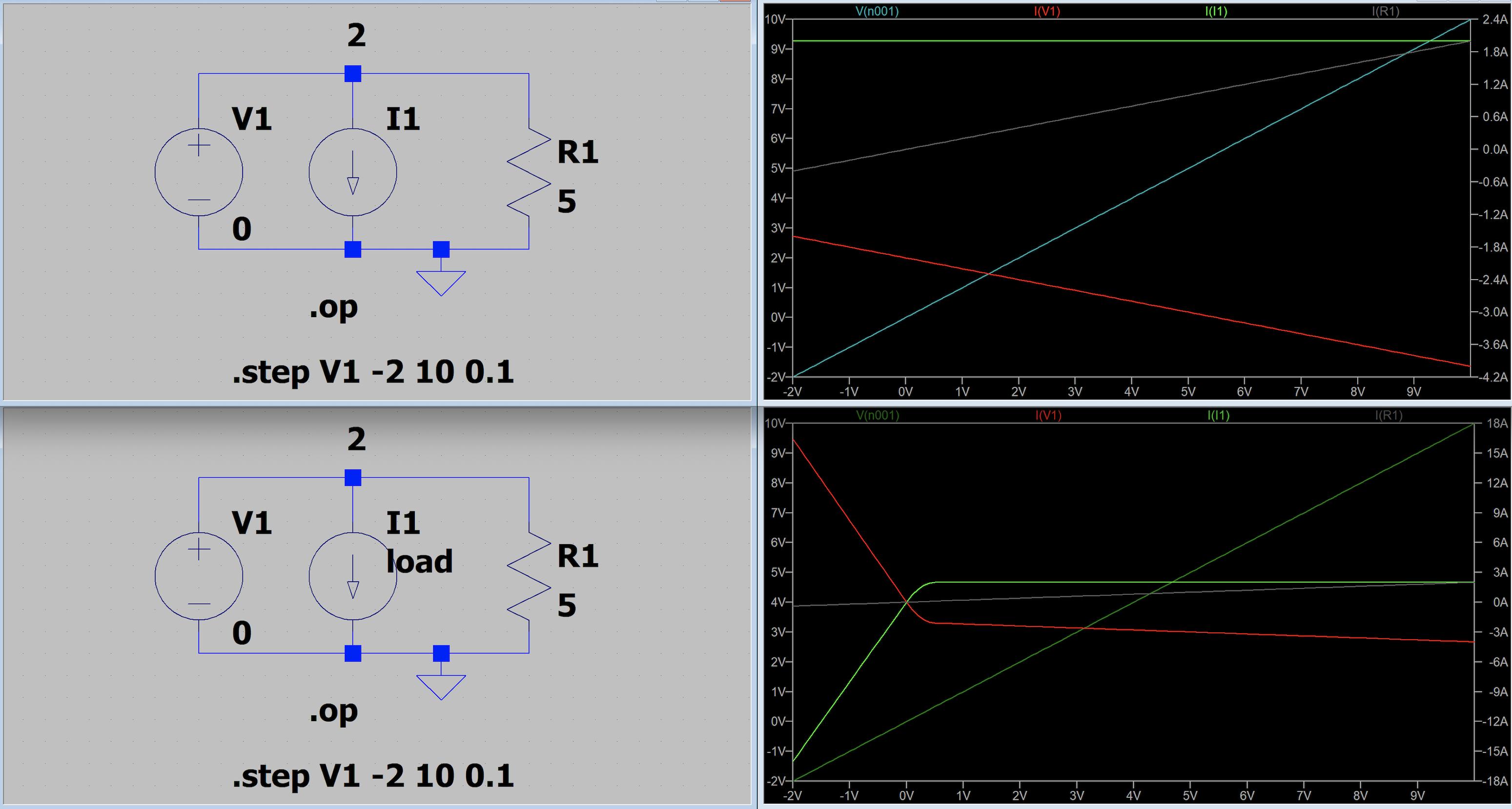
Current Source Active Load

added 272 characters in body
Source Link
KMC
  • 1.4k
  • 3
  • 22
  • 51

I'm having difficulty understanding what Parasitic Properties: This is an active load means in LTSpice given as an option in the current source configuration window. So I plotted out the schematics, one with the active load checked and the other without, and compared their simulated traces. Without being an "active load", the current source behaves just like how a current source should be - a constant 2A current through \$ I_1 \$ (top schematic and trace). But if I check the "active load", the current through \$ I_1 \$ stays constant at 2A only after voltage goes above 0.5V, and down to -16A when \$ V_1 \$ is -2V.

It makes no sense to me that the current source sinks 16A while I've already fixed it a DC value of \$ I_1 = \$ 2A - where is this extra 12A comes from? I can't understand how a load can be modeled as a current source.

  1. It makes no sense to me that the current source can sink 16A while I've already fixed it a DC value of \$ I_1 = \$ 2A - where is this extra 12A comes from?
  2. I don't understand how a load can be modeled as a current source. Isn't a load a component or a sub-circuit that sinks current and dissipates energy? Current source supplies energy to the circuit - how could it supply electrons to the circuit yet dissipating more energy (that \$ 16A*2V=32W \$!) than the rest of circuit?) .

Perhaps a related question here: LTSpice active load current generator soft saturation

Current Source Active Load

I'm having difficulty understanding what Parasitic Properties: This is an active load means in LTSpice given as an option in the current source configuration window. So I plotted out the schematics, one with the active load checked and the other without, and compared their simulated traces. Without being an "active load", the current source behaves just like how a current source should be - a constant 2A current through \$ I_1 \$ (top schematic and trace). But if I check the "active load", the current through \$ I_1 \$ stays constant at 2A only after voltage goes above 0.5V, and down to -16A when \$ V_1 \$ is -2V.

It makes no sense to me that the current source sinks 16A while I've already fixed it a DC value of \$ I_1 = \$ 2A - where is this extra 12A comes from? I can't understand how a load can be modeled as a current source.

Perhaps a related question here: LTSpice active load current generator soft saturation

Current Source Active Load

I'm having difficulty understanding what Parasitic Properties: This is an active load means in LTSpice given as an option in the current source configuration window. So I plotted out the schematics, one with the active load checked and the other without, and compared their simulated traces. Without being an "active load", the current source behaves just like how a current source should be - a constant 2A current through \$ I_1 \$ (top schematic and trace). But if I check the "active load", the current through \$ I_1 \$ stays constant at 2A only after voltage goes above 0.5V, and down to -16A when \$ V_1 \$ is -2V.

  1. It makes no sense to me that the current source can sink 16A while I've already fixed it a DC value of \$ I_1 = \$ 2A - where is this extra 12A comes from?
  2. I don't understand how a load can be modeled as a current source. Isn't a load a component or a sub-circuit that sinks current and dissipates energy? Current source supplies energy to the circuit - how could it supply electrons to the circuit yet dissipating more energy (that \$ 16A*2V=32W \$!) than the rest of circuit?) .

Perhaps a related question here: LTSpice active load current generator soft saturation

Current Source Active Load

Source Link
KMC
  • 1.4k
  • 3
  • 22
  • 51

Setting current source as active load in LTSpice

I'm having difficulty understanding what Parasitic Properties: This is an active load means in LTSpice given as an option in the current source configuration window. So I plotted out the schematics, one with the active load checked and the other without, and compared their simulated traces. Without being an "active load", the current source behaves just like how a current source should be - a constant 2A current through \$ I_1 \$ (top schematic and trace). But if I check the "active load", the current through \$ I_1 \$ stays constant at 2A only after voltage goes above 0.5V, and down to -16A when \$ V_1 \$ is -2V.

It makes no sense to me that the current source sinks 16A while I've already fixed it a DC value of \$ I_1 = \$ 2A - where is this extra 12A comes from? I can't understand how a load can be modeled as a current source.

Perhaps a related question here: LTSpice active load current generator soft saturation

Current Source Active Load