added 8 characters in body
Source Link
winny
  • 16.8k
  • 6
  • 50
  • 71

I am designing a simple H bridge circuit for use with the Atmega8 microcontroller. The DC motor moves this application a lot and generates 140ma140 mA current spikes (DC motor locked) or 60ma60 mA with normal workload.

The working voltage ranges from 10V10 to 16V16 V, I will use the transistors BD441 / BD442 (2A2 A of DC current at 20V20 V and 4A4 A DC at 10V10 V) were the most robust that will fit in my circuit.

H-Bridge with current limit

Q1 to Q5 will be BD441 / 442, some questions:

  • Q5 through R8 (shunt) limits the current (I will leave 200ma peak), it makes sense to use this transistor to limit the inductive current peaks or I could just limit the current through the base of the transistors? What would be the problem of operating the base current transistor to operate in a linear region up to 200ma200 mA?

  • Q6 will be a small npn, together with a 20V20 V zener it makes Q5 cut and stops driving in cases of over voltage. I've seen this DC motor being operated by a transistor with 45 Vce without fail, I wanted more robustness in the circuit, does it make sense to use it or not?

  • Use small resistors (0R33, 0R66 etc.) in the DC motor terminals help protect the circuit against very short surge currents that the oscilloscope cannot see or does my 4 ohm rshunt resistor solve this already?

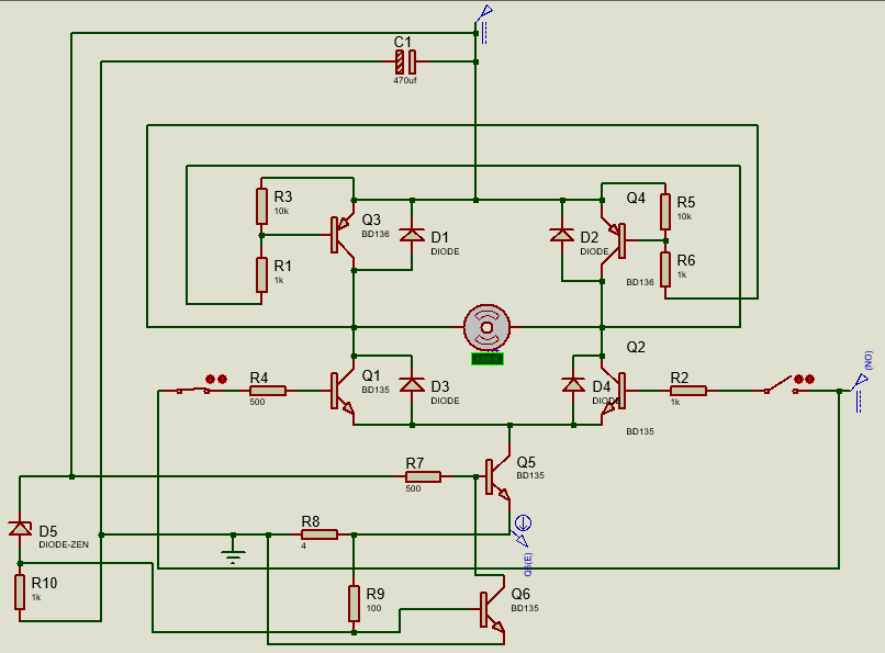
I am designing a simple H bridge circuit for use with the Atmega8 microcontroller. The DC motor moves this application a lot and generates 140ma current spikes (DC motor locked) or 60ma with normal workload.

The working voltage ranges from 10V to 16V, I will use the transistors BD441 / BD442 (2A of DC current at 20V and 4A DC at 10V) were the most robust that will fit in my circuit.

H-Bridge with current limit

Q1 to Q5 will be BD441 / 442, some questions:

  • Q5 through R8 (shunt) limits the current (I will leave 200ma peak), it makes sense to use this transistor to limit the inductive current peaks or I could just limit the current through the base of the transistors? What would be the problem of operating the base current transistor to operate in a linear region up to 200ma?

  • Q6 will be a small npn, together with a 20V zener it makes Q5 cut and stops driving in cases of over voltage. I've seen this DC motor being operated by a transistor with 45 Vce without fail, I wanted more robustness in the circuit, does it make sense to use it or not?

  • Use small resistors (0R33, 0R66 etc.) in the DC motor terminals help protect the circuit against very short surge currents that the oscilloscope cannot see or does my 4 ohm rshunt resistor solve this already?

I am designing a simple H bridge circuit for use with the Atmega8 microcontroller. The DC motor moves this application a lot and generates 140 mA current spikes (DC motor locked) or 60 mA with normal workload.

The working voltage ranges from 10 to 16 V, I will use the transistors BD441 / BD442 (2 A of DC current at 20 V and 4 A DC at 10 V) were the most robust that will fit in my circuit.

H-Bridge with current limit

Q1 to Q5 will be BD441 / 442, some questions:

  • Q5 through R8 (shunt) limits the current (I will leave 200ma peak), it makes sense to use this transistor to limit the inductive current peaks or I could just limit the current through the base of the transistors? What would be the problem of operating the base current transistor to operate in a linear region up to 200 mA?

  • Q6 will be a small npn, together with a 20 V zener it makes Q5 cut and stops driving in cases of over voltage. I've seen this DC motor being operated by a transistor with 45 Vce without fail, I wanted more robustness in the circuit, does it make sense to use it or not?

  • Use small resistors (0R33, 0R66 etc.) in the DC motor terminals help protect the circuit against very short surge currents that the oscilloscope cannot see or does my 4 ohm rshunt resistor solve this already?

Source Link

H-Bridge current limiting

I am designing a simple H bridge circuit for use with the Atmega8 microcontroller. The DC motor moves this application a lot and generates 140ma current spikes (DC motor locked) or 60ma with normal workload.

The working voltage ranges from 10V to 16V, I will use the transistors BD441 / BD442 (2A of DC current at 20V and 4A DC at 10V) were the most robust that will fit in my circuit.

H-Bridge with current limit

Q1 to Q5 will be BD441 / 442, some questions:

  • Q5 through R8 (shunt) limits the current (I will leave 200ma peak), it makes sense to use this transistor to limit the inductive current peaks or I could just limit the current through the base of the transistors? What would be the problem of operating the base current transistor to operate in a linear region up to 200ma?

  • Q6 will be a small npn, together with a 20V zener it makes Q5 cut and stops driving in cases of over voltage. I've seen this DC motor being operated by a transistor with 45 Vce without fail, I wanted more robustness in the circuit, does it make sense to use it or not?

  • Use small resistors (0R33, 0R66 etc.) in the DC motor terminals help protect the circuit against very short surge currents that the oscilloscope cannot see or does my 4 ohm rshunt resistor solve this already?