added 127 characters in body
Source Link
Spehro 'speff' Pefhany
  • 422.8k
  • 23
  • 352
  • 952

Have a look at the typical characteristics of a CD4069UB gate:

enter image description here

As you can see, the gate with no feedback (typically) acts as crude comparator that switches at approximately Vdd/2 (which is 4.5V in this case).

With feedback it can be considered an amplifier with a transfer function as follows:

Vpin1 = 4.5V, Vpin1 = (Vo + Vin)/2 => Vo = 9V-Vin

Now we can easily calculate the transition voltage for each LED from top to bottom, since it's a simple voltage divider (the gate inputs draw negligible current):

enter image description here

The right-hand column indicates the difference to the next LED, which is fairly constant.

It should be mentioned that this circuit works "typically" and there is no guarantee that any given gate will behave that way, in fact if you look at the worst-case characteristics:

enter image description here

.. it may not work very well at all. Also both the transistors are partly 'on' at the transitions (and the input gate is biased so it also has both transistors on) so the circuit draws extra mA that are wasted.

So it's an okay toy, but not really something you'd want to ship.


To make it work from a 5V supply, you can simply reduce the supply voltage and accept that the input voltage will be scaled proportionally. Instead of 0..5V it will be more like 0..2.8V. Use a divider at the input if you want a 0..5V approximately input voltage. There is no control over how 'sharp' the transitions are, you're at the mercy of the physics and fabrication of the inverters.

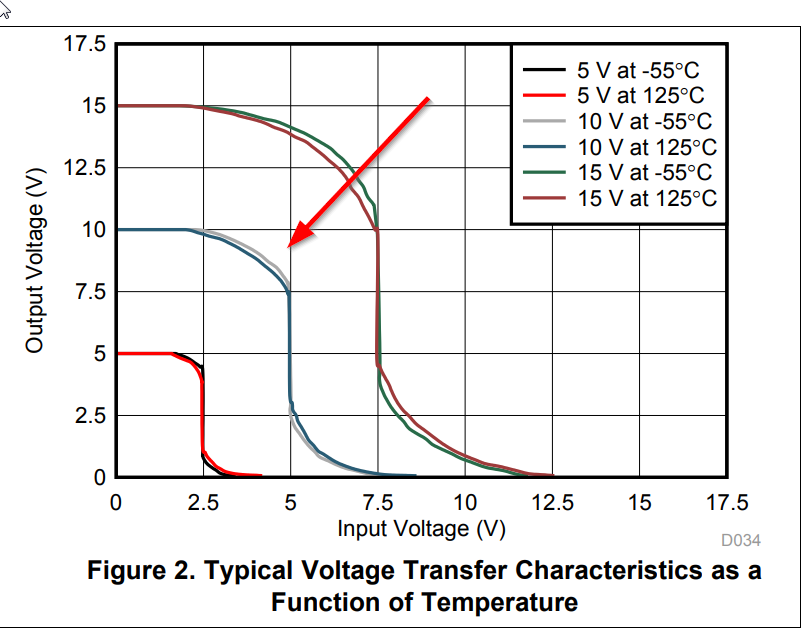
Have a look at the typical characteristics of a CD4069UB gate:

enter image description here

As you can see, the gate with no feedback (typically) acts as crude comparator that switches at approximately Vdd/2 (which is 4.5V in this case).

With feedback it can be considered an amplifier with a transfer function as follows:

Vpin1 = 4.5V, Vpin1 = (Vo + Vin)/2 => Vo = 9V-Vin

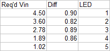
Now we can easily calculate the transition voltage for each LED from top to bottom, since it's a simple voltage divider (the gate inputs draw negligible current):

enter image description here

The right-hand column indicates the difference to the next LED, which is fairly constant.

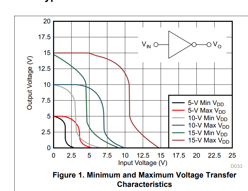
It should be mentioned that this circuit works "typically" and there is no guarantee that any given gate will behave that way, in fact if you look at the worst-case characteristics:

enter image description here

.. it may not work very well at all. Also both the transistors are partly 'on' at the transitions (and the input gate is biased so it also has both transistors on) so the circuit draws extra mA that are wasted.

So it's an okay toy, but not really something you'd want to ship.


To make it work from a 5V supply, you can simply reduce the supply voltage and accept that the input voltage will be scaled proportionally. Instead of 0..5V it will be more like 0..2.8V. Use a divider at the input if you want a 0..5V approximately input voltage.

Have a look at the typical characteristics of a CD4069UB gate:

enter image description here

As you can see, the gate with no feedback (typically) acts as crude comparator that switches at approximately Vdd/2 (which is 4.5V in this case).

With feedback it can be considered an amplifier with a transfer function as follows:

Vpin1 = 4.5V, Vpin1 = (Vo + Vin)/2 => Vo = 9V-Vin

Now we can easily calculate the transition voltage for each LED from top to bottom, since it's a simple voltage divider (the gate inputs draw negligible current):

enter image description here

The right-hand column indicates the difference to the next LED, which is fairly constant.

It should be mentioned that this circuit works "typically" and there is no guarantee that any given gate will behave that way, in fact if you look at the worst-case characteristics:

enter image description here

.. it may not work very well at all. Also both the transistors are partly 'on' at the transitions (and the input gate is biased so it also has both transistors on) so the circuit draws extra mA that are wasted.

So it's an okay toy, but not really something you'd want to ship.


To make it work from a 5V supply, you can simply reduce the supply voltage and accept that the input voltage will be scaled proportionally. Instead of 0..5V it will be more like 0..2.8V. Use a divider at the input if you want a 0..5V approximately input voltage. There is no control over how 'sharp' the transitions are, you're at the mercy of the physics and fabrication of the inverters.
added 77 characters in body
Source Link
Spehro 'speff' Pefhany
  • 422.8k
  • 23
  • 352
  • 952

Have a look at the typical characteristics of a CD4069UB gate:

enter image description here

As you can see, the gate with no feedback (typically) acts as crude comparator that switches at approximately Vdd/2 (which is 4.5V in this case).

With feedback it can be considered an amplifier with a transfer function as follows:

Vpin1 = 4.5V, Vpin1 = (Vo + Vin)/2 => Vo = 9V-Vin

Now we can easily calculate the transition voltage for each LED from top to bottom, since it's a simple voltage divider (the gate inputs draw negligible current):

enter image description here

The right-hand column indicates the difference to the next LED, which is fairly constant.

It should be mentioned that this circuit works "typically" and there is no guarantee that any given gate will behave that way, in fact if you look at the worst-case characteristics:

enter image description here

.. it may not work very well at all. Also both the transistors are partly 'on' at the transitions (and the input gate is biased so it also has both transistors on) so the circuit draws extra mA that are wasted.

So it's an okay toy, but not really something you'd want to ship.


To make it work from a 5V supply, you can simply reduce the supply voltage and accept that the input voltage will be scaled proportionally. Instead of 0..5V it will be more like 0..2.8V. Use a divider at the input if you want a 0..5V approximately input voltage.

Have a look at the typical characteristics of a CD4069UB gate:

enter image description here

As you can see, the gate with no feedback (typically) acts as crude comparator that switches at approximately Vdd/2 (which is 4.5V in this case).

With feedback it can be considered an amplifier with a transfer function as follows:

Vpin1 = 4.5V, Vpin1 = (Vo + Vin)/2 => Vo = 9V-Vin

Now we can easily calculate the transition voltage for each LED from top to bottom, since it's a simple voltage divider (the gate inputs draw negligible current):

enter image description here

The right-hand column indicates the difference to the next LED, which is fairly constant.

It should be mentioned that this circuit works "typically" and there is no guarantee that any given gate will behave that way, in fact if you look at the worst-case characteristics:

enter image description here

.. it may not work very well at all. Also both the transistors are partly 'on' at the transitions (and the input gate is biased so it also has both transistors on) so the circuit draws extra mA that are wasted.

So it's an okay toy, but not really something you'd want to ship.


To make it work from a 5V supply, you can simply reduce the supply voltage and accept that the input voltage will be scaled proportionally. Instead of 0..5V it will be more like 0..2.8V. Use a divider at the input if you want a 0..5V approximately input voltage.

added 77 characters in body
Source Link
Spehro 'speff' Pefhany
  • 422.8k
  • 23
  • 352
  • 952

Have a look at the typical characteristics of a CD4069UB gate:

enter image description here

As you can see, the gate with no feedback (typically) acts as crude comparator that switches at approximately Vdd/2 (which is 4.5V in this case).

With feedback it can be considered an amplifier with a transfer function as follows:

Vpin1 = 4.5V, Vpin1 = (Vo + Vin)/2 => Vo = 9V-Vin

So for Vin = 0..5V, Vo = 4..0V

Now we can easily calculate the transition voltage for each LED from top to bottom, since it's a simple voltage divider (the gate inputs draw negligible current):

enter image description here

The right-hand column indicates the difference to the next LED, which is fairly constant.

It should be mentioned that this circuit works "typically" and there is no guarantee that any given gate will behave that way, in fact if you look at the worst-case characteristics:

enter image description here

.. it may not work very well at all. Also both the transistors are partly 'on' at the transitions (and the input gate is biased so it also has both transistors on) so the circuit draws extra mA that are wasted.

So it's an okay toy, but not really something you'd want to ship.

Have a look at the typical characteristics of a CD4069UB gate:

enter image description here

As you can see, the gate with no feedback (typically) acts as crude comparator that switches at approximately Vdd/2.

With feedback it can be considered an amplifier with a transfer function as follows:

Vpin1 = 4.5V, Vpin1 = (Vo + Vin)/2 => Vo = 9V-Vin

So for Vin = 0..5V, Vo = 4..0V

Now we can easily calculate the transition voltage for each LED from top to bottom:

enter image description here

The right-hand column indicates the difference to the next LED, which is fairly constant.

It should be mentioned that this circuit works "typically" and there is no guarantee that any given gate will behave that way, in fact if you look at the worst-case characteristics:

enter image description here

.. it may not work very well at all. Also both the transistors are partly 'on' at the transitions (and the input gate is biased so it also has both transistors on) so the circuit draws extra mA that are wasted.

So it's an okay toy, but not really something you'd want to ship.

Have a look at the typical characteristics of a CD4069UB gate:

enter image description here

As you can see, the gate with no feedback (typically) acts as crude comparator that switches at approximately Vdd/2 (which is 4.5V in this case).

With feedback it can be considered an amplifier with a transfer function as follows:

Vpin1 = 4.5V, Vpin1 = (Vo + Vin)/2 => Vo = 9V-Vin

Now we can easily calculate the transition voltage for each LED from top to bottom, since it's a simple voltage divider (the gate inputs draw negligible current):

enter image description here

The right-hand column indicates the difference to the next LED, which is fairly constant.

It should be mentioned that this circuit works "typically" and there is no guarantee that any given gate will behave that way, in fact if you look at the worst-case characteristics:

enter image description here

.. it may not work very well at all. Also both the transistors are partly 'on' at the transitions (and the input gate is biased so it also has both transistors on) so the circuit draws extra mA that are wasted.

So it's an okay toy, but not really something you'd want to ship.

Source Link
Spehro 'speff' Pefhany
  • 422.8k
  • 23
  • 352
  • 952
Loading