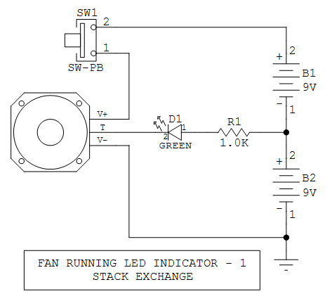
You must check your fan datasheet to see if it will work with this circuit.
Many tach fans have an open-collector tach output signal that can sink at least 10 mA. If yours is like this, then this is about as simple as it gets. A typical fan tach signal is a square wave, with two pulses per revolution, comfortably above 100 Hz to prevent perceived flicker.
Connecting the LED to the 9 V point lowers wasted energy in the current limiting resistor. Also, sometimes the tach output is rated for a max of 12 V even if the fan is running on 18 V or 24 V.
IfUPDATE: To eliminate the center-tap connection between the two batteries, the right side of R1 can be connected to the switch (pin 1). You will have to increase both the resistance value and the power rating. If you need more LED brightness/current, than the next step up addsfan can control directly, you can add one transistor and one resistor.

