Update of rotten link
Source Link
Verbal Kint
  • 23.5k
  • 1
  • 19
  • 57

When I see the amount of lines thrown on the blank page by the OP as an attempt to derive this 3rd-order transfer function, I think it is about time time that fast analytical circuits techniques or FACTs are taught in universities. The principle is simple and, very often, works with inspection: just look at the circuit to infer the time constants without writing a single line of algebra. The exercise consists of determining the resistance \$R\$ offered by each energy-storing element when the circuit is observed with a zeroed excitation or with a nulled response. Once you have the \$R\$, you can form a time constant expressed as \$\tau=RC\$ or \$\tau=\frac{L}{R}\$.

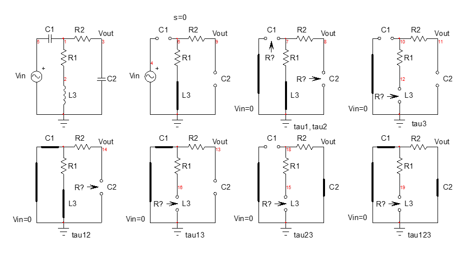
So we start with a bunch of small sketches to determine the natural time constants of this linear circuit. We reduce the excitation to zero volt (the input source is replaced by a short circuit) and you "look" through the energy-storing element temporarily disconnected from the circuit to find the resistance \$R\$ driving that element:

enter image description here

As you can see, you just inspect the drawing to see, in your head, what resistance the terminals in question offer (where the arrow points). And if you make a mistake, it is easy and fast to come back to the circuit and correct the resistance \$R\$ you mistakenly determined.

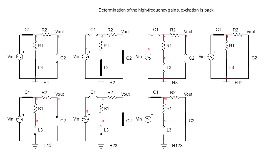
For the zeroes, you can do what is a called a null double injection (NDI) but I often prefer for the passive case, to determine high-frequency gains: the source is back in place and you inspect the circuit to determine what the gains are when energy-storing elements are alternately placed in their high-frequency state:

enter image description here

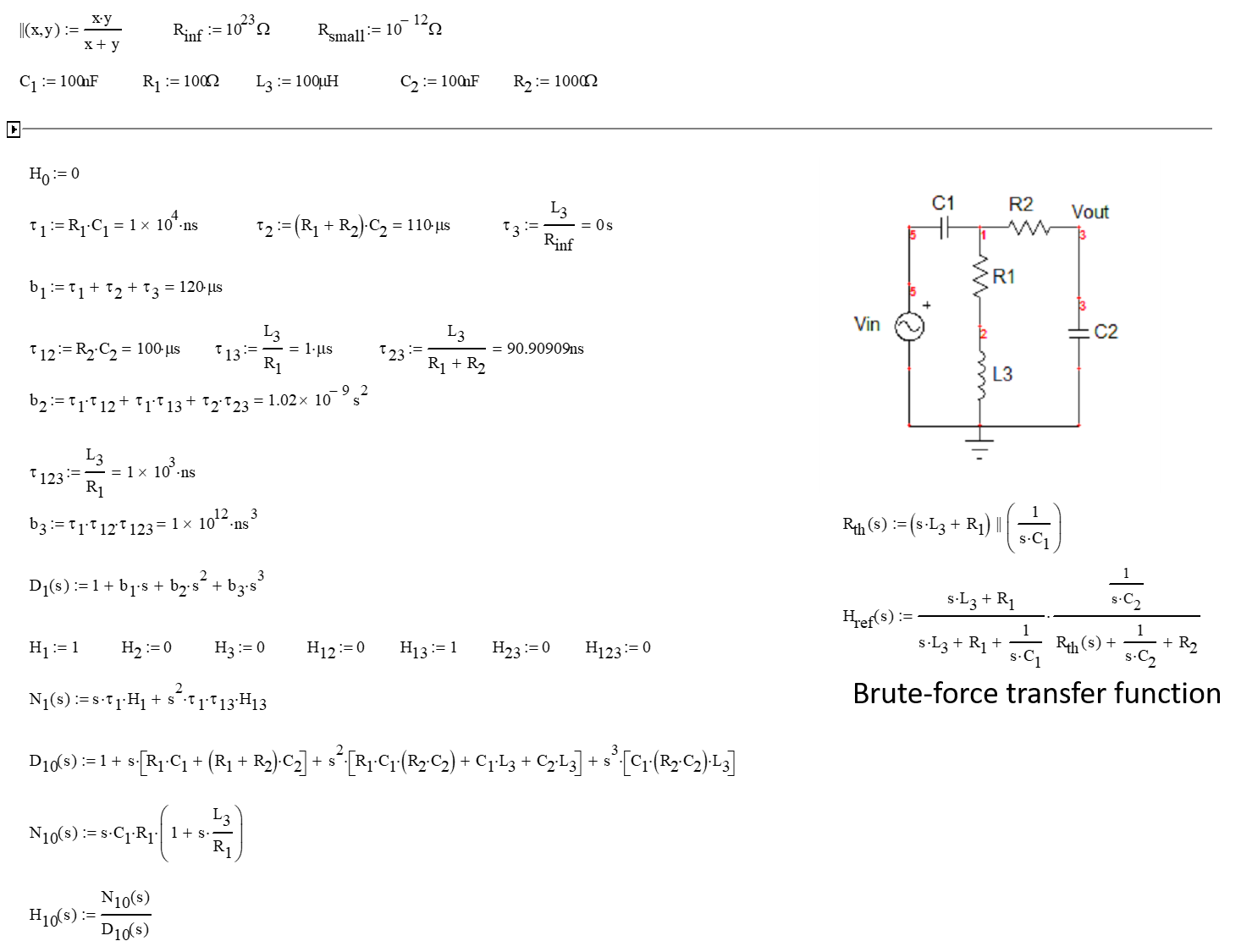
You can see how easy it is! When you have all these elements on hand, you assemble them in a Mathcad sheet which a) will check homogeneity of the formulas and b) will let you compare the response obtained by the FACTs and that delivered by the brute-force approach (Thévenin in this case):

enter image description here

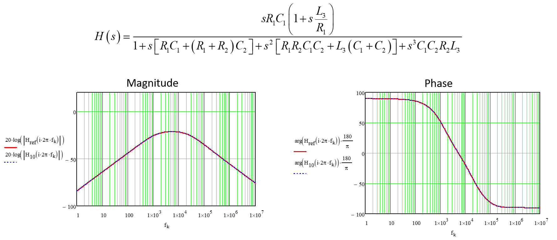
Then you can plot the magnitude and phase while comparing the two responses in similar plots. They perfectly match as shown below:

enter image description here

You can see how easy the FACTs are compared to the classical KVL and KCL methods. You apply the divide-and-conquer strategy promoted by Dr. Middlebrook and solve your circuit step-by-step with the ability to come back and solve an intermediate wrong result. There is no way you can do that with the brute-force approach.

Acquiring the FACTs skill is simple and you can start with 1st-order circuits as shown in the APEC seminarAPEC seminar I taught in 2016. Then, for an in-depth description of the method up to the order \$N\$, you can have a look at the book I published on the subject.

When I see the amount of lines thrown on the blank page by the OP as an attempt to derive this 3rd-order transfer function, I think it is about time time that fast analytical circuits techniques or FACTs are taught in universities. The principle is simple and, very often, works with inspection: just look at the circuit to infer the time constants without writing a single line of algebra. The exercise consists of determining the resistance \$R\$ offered by each energy-storing element when the circuit is observed with a zeroed excitation or with a nulled response. Once you have the \$R\$, you can form a time constant expressed as \$\tau=RC\$ or \$\tau=\frac{L}{R}\$.

So we start with a bunch of small sketches to determine the natural time constants of this linear circuit. We reduce the excitation to zero volt (the input source is replaced by a short circuit) and you "look" through the energy-storing element temporarily disconnected from the circuit to find the resistance \$R\$ driving that element:

enter image description here

As you can see, you just inspect the drawing to see, in your head, what resistance the terminals in question offer (where the arrow points). And if you make a mistake, it is easy and fast to come back to the circuit and correct the resistance \$R\$ you mistakenly determined.

For the zeroes, you can do what is a called a null double injection (NDI) but I often prefer for the passive case, to determine high-frequency gains: the source is back in place and you inspect the circuit to determine what the gains are when energy-storing elements are alternately placed in their high-frequency state:

enter image description here

You can see how easy it is! When you have all these elements on hand, you assemble them in a Mathcad sheet which a) will check homogeneity of the formulas and b) will let you compare the response obtained by the FACTs and that delivered by the brute-force approach (Thévenin in this case):

enter image description here

Then you can plot the magnitude and phase while comparing the two responses in similar plots. They perfectly match as shown below:

enter image description here

You can see how easy the FACTs are compared to the classical KVL and KCL methods. You apply the divide-and-conquer strategy promoted by Dr. Middlebrook and solve your circuit step-by-step with the ability to come back and solve an intermediate wrong result. There is no way you can do that with the brute-force approach.

Acquiring the FACTs skill is simple and you can start with 1st-order circuits as shown in the APEC seminar I taught in 2016. Then, for an in-depth description of the method up to the order \$N\$, you can have a look at the book I published on the subject.
Source Link
Verbal Kint
  • 23.5k
  • 1
  • 19
  • 57

When I see the amount of lines thrown on the blank page by the OP as an attempt to derive this 3rd-order transfer function, I think it is about time time that fast analytical circuits techniques or FACTs are taught in universities. The principle is simple and, very often, works with inspection: just look at the circuit to infer the time constants without writing a single line of algebra. The exercise consists of determining the resistance \$R\$ offered by each energy-storing element when the circuit is observed with a zeroed excitation or with a nulled response. Once you have the \$R\$, you can form a time constant expressed as \$\tau=RC\$ or \$\tau=\frac{L}{R}\$.

So we start with a bunch of small sketches to determine the natural time constants of this linear circuit. We reduce the excitation to zero volt (the input source is replaced by a short circuit) and you "look" through the energy-storing element temporarily disconnected from the circuit to find the resistance \$R\$ driving that element:

enter image description here

As you can see, you just inspect the drawing to see, in your head, what resistance the terminals in question offer (where the arrow points). And if you make a mistake, it is easy and fast to come back to the circuit and correct the resistance \$R\$ you mistakenly determined.

For the zeroes, you can do what is a called a null double injection (NDI) but I often prefer for the passive case, to determine high-frequency gains: the source is back in place and you inspect the circuit to determine what the gains are when energy-storing elements are alternately placed in their high-frequency state:

enter image description here

You can see how easy it is! When you have all these elements on hand, you assemble them in a Mathcad sheet which a) will check homogeneity of the formulas and b) will let you compare the response obtained by the FACTs and that delivered by the brute-force approach (Thévenin in this case):

enter image description here

Then you can plot the magnitude and phase while comparing the two responses in similar plots. They perfectly match as shown below:

enter image description here

You can see how easy the FACTs are compared to the classical KVL and KCL methods. You apply the divide-and-conquer strategy promoted by Dr. Middlebrook and solve your circuit step-by-step with the ability to come back and solve an intermediate wrong result. There is no way you can do that with the brute-force approach.

Acquiring the FACTs skill is simple and you can start with 1st-order circuits as shown in the APEC seminar I taught in 2016. Then, for an in-depth description of the method up to the order \$N\$, you can have a look at the book I published on the subject.