Added 555 version
Source Link
Oli Glaser
  • 55.5k
  • 3
  • 77
  • 148

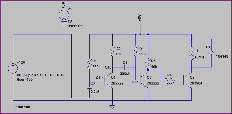
Insta is right, a 555 is simple to setup for this and costs less than a dollar. I was thinking you were including something like the 555 in your considerations, but just in case here is a possible transistor only solution (parts shown and values are guidlelines, circuit is rough and could be improved, but it's gives the idea - time will vary with components chosen, so you may need to tweak things a bit, add a pot instead of the R1/R7, etc)

Circuit:
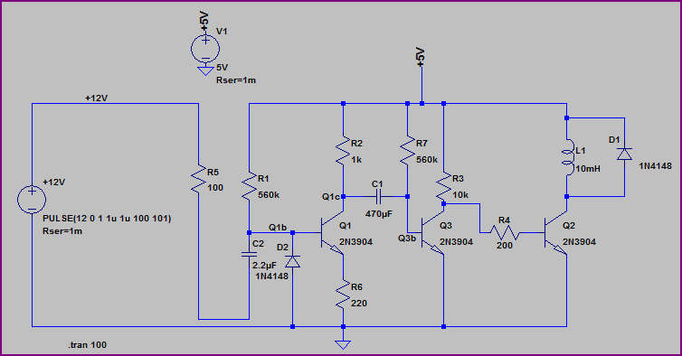
Power Off Relay Drive

Simulation:

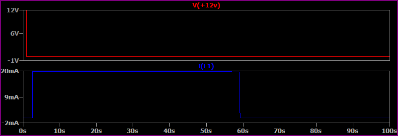
Circuit Simulation

L1 is your relay coil, and is powered for roughly 60 seconds on the 12V supply dropping out. C2 may need to be increased if the +12V supply drops slowly.

555 Solution

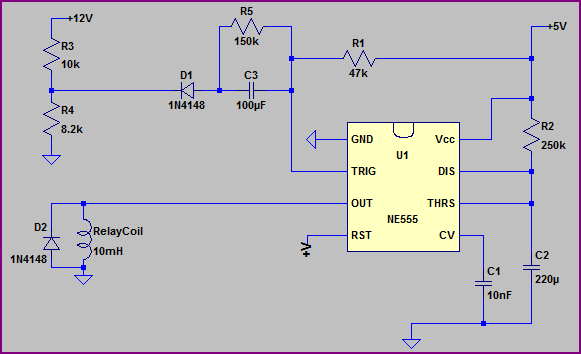
Here is a version based around the trusty old 555 timer IC:
555 Version

Depending on how fast the 12V supply drops, you may need to increase C3 (if it drops slowly) Again values are guidelines, you can tweak as necessary. The R3/R4 divider stops the voltage going negative at the trigger input, which might cause issues.
The diode (D1) can probably also be included in a similar fashion with the first circuit (in series with R5) to stop the power on pulse you mentioned (you would also need a large value resistor from the input side of C2 to +5V)

Simulation:
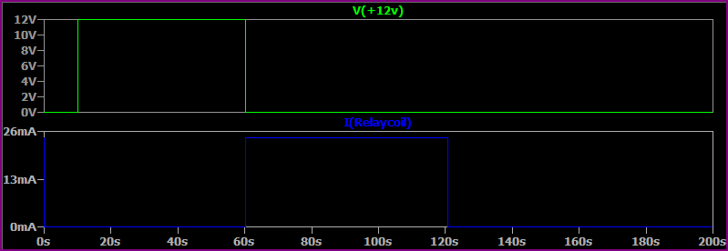
555 Version Simulation

Insta is right, a 555 is simple to setup for this and costs less than a dollar. I was thinking you were including something like the 555 in your considerations, but just in case here is a possible transistor only solution (parts shown and values are guidlelines, circuit is rough and could be improved, but it's gives the idea - time will vary with components chosen, so you may need to tweak things a bit, add a pot instead of the R1/R7, etc)

Circuit:

Power Off Relay Drive

Simulation:

Circuit Simulation

L1 is your relay coil, and is powered for roughly 60 seconds on the 12V supply dropping out.

Insta is right, a 555 is simple to setup for this and costs less than a dollar. I was thinking you were including something like the 555 in your considerations, but just in case here is a possible transistor only solution (parts shown and values are guidlelines, circuit is rough and could be improved, but it's gives the idea - time will vary with components chosen, so you may need to tweak things a bit, add a pot instead of the R1/R7, etc)

Circuit:

Power Off Relay Drive

Simulation:

Circuit Simulation

L1 is your relay coil, and is powered for roughly 60 seconds on the 12V supply dropping out. C2 may need to be increased if the +12V supply drops slowly.

555 Solution

Here is a version based around the trusty old 555 timer IC:

555 Version

Depending on how fast the 12V supply drops, you may need to increase C3 (if it drops slowly) Again values are guidelines, you can tweak as necessary. The R3/R4 divider stops the voltage going negative at the trigger input, which might cause issues.
The diode (D1) can probably also be included in a similar fashion with the first circuit (in series with R5) to stop the power on pulse you mentioned (you would also need a large value resistor from the input side of C2 to +5V)

Simulation:

555 Version Simulation

added 85 characters in body
Source Link
Oli Glaser
  • 55.5k
  • 3
  • 77
  • 148

Insta is right, a 555 is simple to setup for this and costs less than a dollar. I was thinking you were including something like the 555 in your considerations, but just in case here is a possible transistor only solution (parts shown and values are guidlelines, circuit is rough and could be improved, but it's gives the idea - time will vary with components chosen, so you may need to tweak things a bit, add a pot instead of the R1/R7, etc)

Circuit:

Power Off Relay DrivePower Off Relay Drive

Simulation:

Circuit Simulation

L1 is your relay coil, and is powered for roughly 60 seconds on the 12V supply dropping out.

Insta is right, a 555 is simple to setup for this and costs less than a dollar. I was thinking you were including something like the 555 in your considerations, but just in case here is a possible transistor only solution (parts shown and values are guidlelines, circuit is rough and could be improved, but it's gives the idea)

Circuit:

Power Off Relay Drive

Simulation:

Circuit Simulation

L1 is your relay coil, and is powered for roughly 60 seconds on the 12V supply dropping out.

Insta is right, a 555 is simple to setup for this and costs less than a dollar. I was thinking you were including something like the 555 in your considerations, but just in case here is a possible transistor only solution (parts shown and values are guidlelines, circuit is rough and could be improved, but it's gives the idea - time will vary with components chosen, so you may need to tweak things a bit, add a pot instead of the R1/R7, etc)

Circuit:

Power Off Relay Drive

Simulation:

Circuit Simulation

L1 is your relay coil, and is powered for roughly 60 seconds on the 12V supply dropping out.

Source Link
Oli Glaser
  • 55.5k
  • 3
  • 77
  • 148

Insta is right, a 555 is simple to setup for this and costs less than a dollar. I was thinking you were including something like the 555 in your considerations, but just in case here is a possible transistor only solution (parts shown and values are guidlelines, circuit is rough and could be improved, but it's gives the idea)

Circuit:

Power Off Relay Drive

Simulation:

Circuit Simulation

L1 is your relay coil, and is powered for roughly 60 seconds on the 12V supply dropping out.