I am specifically asking whether the driving circuit will see the transmission line as a pure resistance according The Telegrapher's Equations, or whether those equations predict the driving circuit will see a more complex load.
The telegrapher's equations do not indicate that the impedance seen by the source is a pure resistance. They only indicate that the impedance is: -
$$\sqrt{\dfrac{R + j\omega L}{G + j\omega C}}$$
So then you can mess with R, L, G and C and get some more complexity but, if you are prepared to put up with some losses you can make the ratio of R:L the same as G:C and you get what is known as a distortionless line (also defined as the Heaviside condition).
And, for this case, the input impedance is constant irrespective of frequency. It's also purely resistive.
Clearly, for a non-distortionless t-line, at quite high frequencies the impedance is \$\sqrt{\frac{L}{C}}\$ and this is also a resistive input impedance.
For audio (on a fairly loss-less line) it cannot behave distortionlessly because G is normally very, very small and R usually is much greater than \$j\omega L\$ (at audio) hence, the impedance tends to become this: -
$$\sqrt{\dfrac{R}{j\omega C}}$$
At DC, the impedance has to become this: -
$$\sqrt{\dfrac{R}{G}}$$
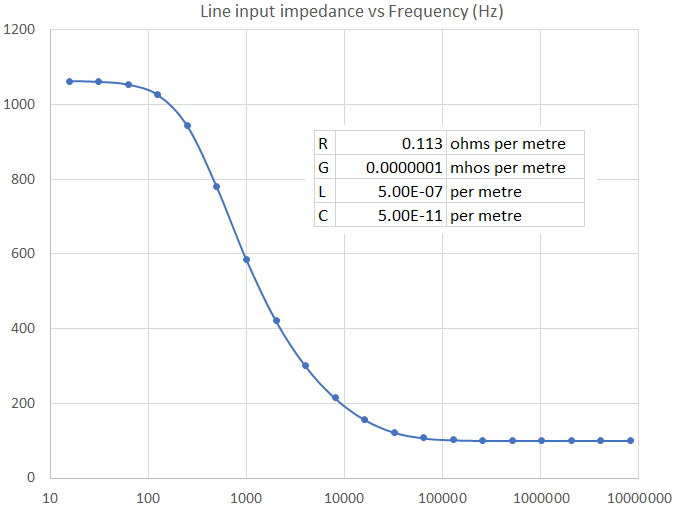
So, you can see that a fairly low loss-less infinite line will have an input impedance like this: -
This impedance magnitude graph was made in Microsoft excel using the four variables shown (approximately what a telephone cable would be). Note that at around 1 kHz, the impedance is about 600 Ω. This is important in regular telephony and is the "standard" impedance used for audio transmission.
Impedance formula magnitude (not too hard to prove): -
$$|Z_0| = \sqrt{\sqrt{\dfrac{R^2+\omega^2 L^2}{G^2+\omega^2 C^2}}}$$
Impedance formula angle (a tad harder to prove): -
$$\text{Angle} = \dfrac{\arctan\left[{\dfrac{\omega\cdot (LG-CR)}{RG+\omega^2 LC}}\right]}{2}$$
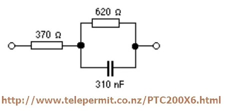
Also note that theThe 600 Ω point mentioned and shown above will be complex and not"complex" (not 100% resistive) hence, for telephone anti-side-tone circuits they tend to balance using this impedance: -
This circuit is a decent representation of a typical telephone cable across the lower audio bandwidth.
When the switch is closed, what will be the voltage and current waveforms at the driven end of the transmission line?
Once you have decided what the t-line input impedance is (it equals the characteristic impedance for an infinite line over all time) then it's simple impedance divider maths using R1 and Zin.
When the switch is closed, what will be the voltage and current waveforms at the driven end of the transmission line?
Only when the line is distortionless or the frequency is high enough to disregard R and G.
Also for reference, the impedance of a lossy transmission line is frequency dependent
It's usually frequency dependent but not so for a distortionless line.


