Became Hot Network Question
deleted 11 characters in body
Source Link
Voltage Spike
  • 88.8k
  • 49
  • 90
  • 234

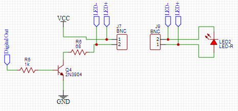
I'm trying to turn on an LED using an NPN transistor as a switch. The catch is, the LED is at the end of a BNC cable, and in my current design, both the outer and inner BNC conductors are normally at 5V when the LED is off. This is inconvenient, because the outer BNC conductor is exposed at the connector and can get shorted to other stuff lying around, so I've had to cover it with electrical tape.

Here's a simplified diagram of my setup:

enter image description here

I thought about moving the LED part of the circuit to the emitter of the transistor instead of the collector, so the BNC conductors would both be grounded normally, but I believe the logic level required to activate the transistor would increase, and I'd need to step up the digital out voltage (please correct me if I'm wrong!)

I can think of three options:

  1. Figure out a better circuit that keeps the LED- pin grounded at all times
  2. Continue wrapping the BNC connector in electrical tape
  3. Get a different connector that isn't BNC where there are no exposed conductors.

I'd prefer option #1, but I'm not sure how to do it - any ideas?

I know this isn't the usual use case for BNC connectors, but it was the best thing I had lying around for the prototype. It seems like there should be a simple way to do this so the negative LED pin is always grounded.

Thanks!

Edit: My digital out is 0-3.3V, and Vcc is around 5.2V
I'm trying to turn on an LED using an NPN transistor as a switch. The catch is, the LED is at the end of a BNC cable, and in my current design, both the outer and inner BNC conductors are normally at 5V when the LED is off. This is inconvenient, because the outer BNC conductor is exposed at the connector and can get shorted to other stuff lying around, so I've had to cover it with electrical tape.

Here's a simplified diagram of my setup:

enter image description here

I thought about moving the LED part of the circuit to the emitter of the transistor instead of the collector, so the BNC conductors would both be grounded normally, but I believe the logic level required to activate the transistor would increase, and I'd need to step up the digital out voltage (please correct me if I'm wrong!)

I can think of three options:

  1. Figure out a better circuit that keeps the LED- pin grounded at all times
  2. Continue wrapping the BNC connector in electrical tape
  3. Get a different connector that isn't BNC where there are no exposed conductors.

I'd prefer option #1, but I'm not sure how to do it - any ideas?

I know this isn't the usual use case for BNC connectors, but it was the best thing I had lying around for the prototype. It seems like there should be a simple way to do this so the negative LED pin is always grounded.

Edit: My digital out is 0-3.3V, and Vcc is around 5.2V

Added extra info about voltages
Source Link

I'm trying to turn on an LED using an NPN transistor as a switch. The catch is, the LED is at the end of a BNC cable, and in my current design, both the outer and inner BNC conductors are normally at 5V when the LED is off. This is inconvenient, because the outer BNC conductor is exposed at the connector and can get shorted to other stuff lying around, so I've had to cover it with electrical tape.

Here's a simplified diagram of my setup:

enter image description here

I thought about moving the LED part of the circuit to the emitter of the transistor instead of the collector, so the BNC conductors would both be grounded normally, but I believe the logic level required to activate the transistor would increase, and I'd need to step up the digital out voltage (please correct me if I'm wrong!)

I can think of three options:

  1. Figure out a better circuit that keeps the LED- pin grounded at all times
  2. Continue wrapping the BNC connector in electrical tape
  3. Get a different connector that isn't BNC where there are no exposed conductors.

I'd prefer option #1, but I'm not sure how to do it - any ideas?

I know this isn't the usual use case for BNC connectors, but it was the best thing I had lying around for the prototype. It seems like there should be a simple way to do this so the negative LED pin is always grounded.

Thanks!

Edit: My digital out is 0-3.3V, and Vcc is around 5.2V

I'm trying to turn on an LED using an NPN transistor as a switch. The catch is, the LED is at the end of a BNC cable, and in my current design, both the outer and inner BNC conductors are normally at 5V when the LED is off. This is inconvenient, because the outer BNC conductor is exposed at the connector and can get shorted to other stuff lying around, so I've had to cover it with electrical tape.

Here's a simplified diagram of my setup:

enter image description here

I thought about moving the LED part of the circuit to the emitter of the transistor instead of the collector, so the BNC conductors would both be grounded normally, but I believe the logic level required to activate the transistor would increase, and I'd need to step up the digital out voltage (please correct me if I'm wrong!)

I can think of three options:

  1. Figure out a better circuit that keeps the LED- pin grounded at all times
  2. Continue wrapping the BNC connector in electrical tape
  3. Get a different connector that isn't BNC where there are no exposed conductors.

I'd prefer option #1, but I'm not sure how to do it - any ideas?

I know this isn't the usual use case for BNC connectors, but it was the best thing I had lying around for the prototype. It seems like there should be a simple way to do this so the negative LED pin is always grounded.

Thanks!

Edit: My digital out is 0-3.3V, and Vcc is around 5.2V

Source Link

How to turn on LED with transistor without exposing a 5V conductor

I'm trying to turn on an LED using an NPN transistor as a switch. The catch is, the LED is at the end of a BNC cable, and in my current design, both the outer and inner BNC conductors are normally at 5V when the LED is off. This is inconvenient, because the outer BNC conductor is exposed at the connector and can get shorted to other stuff lying around, so I've had to cover it with electrical tape.

Here's a simplified diagram of my setup:

enter image description here

I thought about moving the LED part of the circuit to the emitter of the transistor instead of the collector, so the BNC conductors would both be grounded normally, but I believe the logic level required to activate the transistor would increase, and I'd need to step up the digital out voltage (please correct me if I'm wrong!)

I can think of three options:

  1. Figure out a better circuit that keeps the LED- pin grounded at all times
  2. Continue wrapping the BNC connector in electrical tape
  3. Get a different connector that isn't BNC where there are no exposed conductors.

I'd prefer option #1, but I'm not sure how to do it - any ideas?

I know this isn't the usual use case for BNC connectors, but it was the best thing I had lying around for the prototype. It seems like there should be a simple way to do this so the negative LED pin is always grounded.

Thanks!