I decided to try winding a toroid. I used a T 80-2 (red, which should be good below 30MHz) with 23:3 turns
There is no evidence that the toroid you picked is actually any good below 30 MHz at all. You need to examine the data sheet and the performance graphs for the material to make this judgement. In my experience, you cannot assume it will be any good.
Anyway, moving on, let's assume it is good for frequencies up to 30 MHz. To make this assumption and knowing that it is a toroid (no gaps) it must be made from specialist low permeability material. It might have an inductance factor in the region of 100 nH per single turn for it to be good up to 30 MHz.
With three turns, that's a total primary inductance of 900 nH. If your operating frequency is (say) 10 MHz, 900 nH has an impedance (irrespective of what you connect to the secondary) of 56.5 ohms reactive. At 1 MHz the impedance is 5.65 ohms reactive.
So, if your testing frequency is 1 MHz (or lower), it's going to have a pretty shabby input impedance and not at all operate as an impedance transformer.
New information about the core
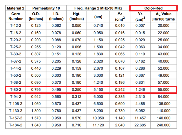
The above table extracted from this data sheet.
As I suspected; it's a very low permeability core with 100 turns producing an inductance of 55 μH. Given that inductance is proportional to the square of the turns, the inductance of 1 turn will be 100² lower at 5.5 nH. Hence, 3 turns will be about 50 nH. At 10 MHz, this has a loading impedance of 3.11 Ω reactive and will just get linearly worse at lower frequencies.
When you are designing an impedance transformer you want the loading impedance of the primary inductance to be significantly higher than the impedance projected to your primary from the secondary.
Can anyone explain how to measure an impedance transformer?
It sounds like you are measuring it correctly with the signal generator but, you are anticipating an ideal impedance transformer and neglecting the very significant effect of the primary loading (magnetization) inductance. Thus, your results confuse you because you are expecting to see about 50 Ω when, in fact you are seeing closer to zero ohms. You should also state what test frequency you used so I can give a better numerical answer.

