added 178 characters in body
Source Link
GeBJT
  • 444
  • 2
  • 5

The Colpitts oscillator is difficult to analyse accurately, but there are versions around which are stable enough for experimenting in simulation and real prototypes. For example:

Colpitts 6 MHz

https://www.circuitlab.com/circuit/2z4bxtfb5jtg/colpitts-6mhz/

This circuit starts oscilation in class-A and once the amplitude is high enough moves to class-C. The class-C mode gives amplitude stability and a fairly clean waveform at "collector"; better shape but lower amplitude at "emitter". The "kick-start" switch is an artifact of simulation - not needed in the real world.

I have built a breadboard / proto-board version and it works very much as the simulation.

how does one control the output level of this kind of circuit?

The tank circuit of this configuration is self-limiting with an amplitude of approx. half the supply rail.

how do I get this thing to run at a useful frequency?

ThisThe configuration in this answer has higher Q, I thinka common base amplifier, thanless susceptible to the Miller effect. Also probably higher Q because of series resonance (the version in your question is parallel resonant for which it is more difficult to control damping).

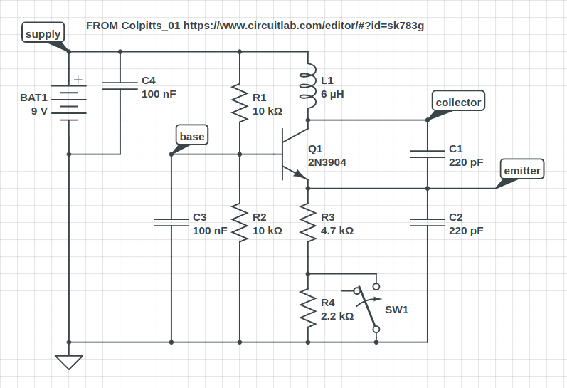
The Colpitts oscillator is difficult to analyse accurately, but there are versions around which are stable enough for experimenting in simulation and real prototypes. For example:

Colpitts 6 MHz

https://www.circuitlab.com/circuit/2z4bxtfb5jtg/colpitts-6mhz/

This circuit starts oscilation in class-A and once the amplitude is high enough moves to class-C. The class-C mode gives amplitude stability and a fairly clean waveform at "collector"; better shape but lower amplitude at "emitter". The "kick-start" switch is an artifact of simulation - not needed in the real world.

I have built a breadboard / proto-board version and it works very much as the simulation.

how does one control the output level of this kind of circuit?

The tank circuit of this configuration is self-limiting with an amplitude of approx. half the supply rail.

how do I get this thing to run at a useful frequency?

This configuration has higher Q, I think, than the version in your question.

The Colpitts oscillator is difficult to analyse accurately, but there are versions around which are stable enough for experimenting in simulation and real prototypes. For example:

Colpitts 6 MHz

https://www.circuitlab.com/circuit/2z4bxtfb5jtg/colpitts-6mhz/

This circuit starts oscilation in class-A and once the amplitude is high enough moves to class-C. The class-C mode gives amplitude stability and a fairly clean waveform at "collector"; better shape but lower amplitude at "emitter". The "kick-start" switch is an artifact of simulation - not needed in the real world.

I have built a breadboard / proto-board version and it works very much as the simulation.

how does one control the output level of this kind of circuit?

The tank circuit of this configuration is self-limiting with an amplitude of approx. half the supply rail.

how do I get this thing to run at a useful frequency?

The configuration in this answer has a common base amplifier, less susceptible to the Miller effect. Also probably higher Q because of series resonance (the version in your question is parallel resonant for which it is more difficult to control damping).

added 5 characters in body
Source Link
GeBJT
  • 444
  • 2
  • 5

The Colpitts oscillator is difficult to analyse accurately, but there are versions around which are stable enough for experimenting in simulation and real prototypes. For example:

Colpitts 6 MHz

https://www.circuitlab.com/circuit/2z4bxtfb5jtg/colpitts-6mhz/

This circuit starts oscilation in class-A and once the amplitude is high enough moves to class-C. The class-C mode gives amplitude stability and a fairly clean waveform at "collector"; better shape but lower amplitude at "emitter". The "kick-start" switch is an artifact of simulation - not needed in the real world.

I have built a breadboard / proto-board version and it works very much as the simulation.

how does one control the output level of this kind of circuit?

The tank circuit of this configuration is self-limiting with an amplitude of approx. half the supply rail.

how do I get this thing to run at a useful frequency?

This configuration has higher Q, I think, than the version in your question.

The Colpitts oscillator is difficult to analyse accurately, but there are versions around which are stable enough for experimenting in simulation and real prototypes. For example:

Colpitts 6 MHz

https://www.circuitlab.com/circuit/2z4bxtfb5jtg/colpitts-6mhz/

This circuit starts oscilation in class-A and once the amplitude is high enough moves to class-C. The class-C mode gives amplitude stability and a fairly clean waveform at "collector"; better shape but lower amplitude at "emitter". The "kick-start" switch is an artifact of simulation - not needed in the real world.

I have built a breadboard / proto-board version and it works very much as the simulation.

how does one control the output level of this kind of circuit?

The tank circuit of this configuration is self-limiting with an amplitude of approx. the supply rail.

how do I get this thing to run at a useful frequency?

This configuration has higher Q, I think, than the version in your question.

The Colpitts oscillator is difficult to analyse accurately, but there are versions around which are stable enough for experimenting in simulation and real prototypes. For example:

Colpitts 6 MHz

https://www.circuitlab.com/circuit/2z4bxtfb5jtg/colpitts-6mhz/

This circuit starts oscilation in class-A and once the amplitude is high enough moves to class-C. The class-C mode gives amplitude stability and a fairly clean waveform at "collector"; better shape but lower amplitude at "emitter". The "kick-start" switch is an artifact of simulation - not needed in the real world.

I have built a breadboard / proto-board version and it works very much as the simulation.

how does one control the output level of this kind of circuit?

The tank circuit of this configuration is self-limiting with an amplitude of approx. half the supply rail.

how do I get this thing to run at a useful frequency?

This configuration has higher Q, I think, than the version in your question.

Source Link
GeBJT
  • 444
  • 2
  • 5

The Colpitts oscillator is difficult to analyse accurately, but there are versions around which are stable enough for experimenting in simulation and real prototypes. For example:

Colpitts 6 MHz

https://www.circuitlab.com/circuit/2z4bxtfb5jtg/colpitts-6mhz/

This circuit starts oscilation in class-A and once the amplitude is high enough moves to class-C. The class-C mode gives amplitude stability and a fairly clean waveform at "collector"; better shape but lower amplitude at "emitter". The "kick-start" switch is an artifact of simulation - not needed in the real world.

I have built a breadboard / proto-board version and it works very much as the simulation.

how does one control the output level of this kind of circuit?

The tank circuit of this configuration is self-limiting with an amplitude of approx. the supply rail.

how do I get this thing to run at a useful frequency?

This configuration has higher Q, I think, than the version in your question.