added 98 characters in body
Source Link

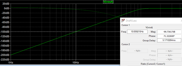
I simulated a 5th order active high pass filter on LTSpice. However I find that the output voltage does not have same attenuation as the magnitude response plot.

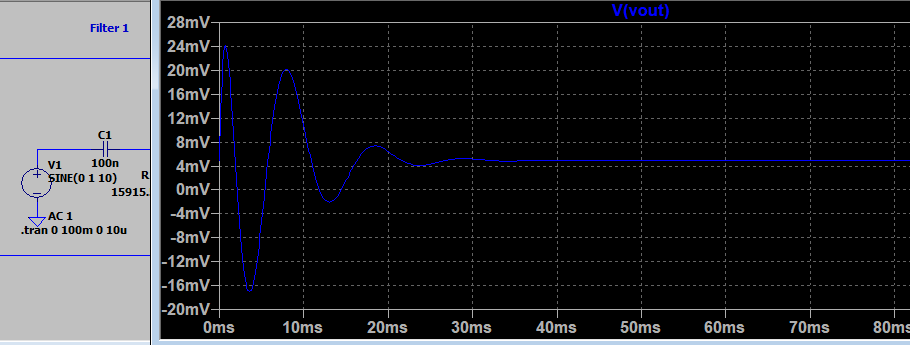
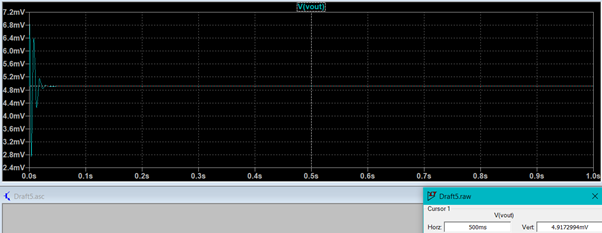
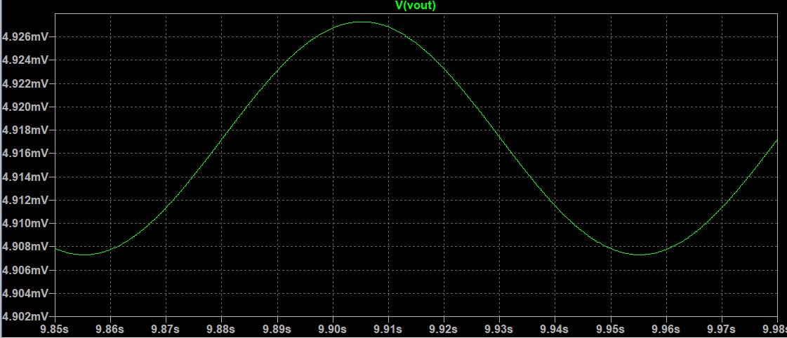
At 10Hz it is expected to have a 100dB attenuation which should yield 10uV. However, the transient simulation shows that the output voltage is 4.91mV which is only -46dB with respect to a 1V 10Hz input.

Is this some form of op-amp saturation or an error in the circuit? I'm still new to simulating circuits.

enter image description here

enter image description here

enter image description here

EDIT: TRANSIENT SIMULATION INPUT enter image description here

EDIT 23:

enter image description hereenter image description here

I simulated a 5th order active high pass filter on LTSpice. However I find that the output voltage does not have same attenuation as the magnitude response plot.

At 10Hz it is expected to have a 100dB attenuation which should yield 10uV. However, the transient simulation shows that the output voltage is 4.91mV which is only -46dB with respect to a 1V 10Hz input.

Is this some form of op-amp saturation or an error in the circuit? I'm still new to simulating circuits.

enter image description here

enter image description here

enter image description here

EDIT: TRANSIENT SIMULATION INPUT enter image description here

EDIT 2:

enter image description here

I simulated a 5th order active high pass filter on LTSpice. However I find that the output voltage does not have same attenuation as the magnitude response plot.

At 10Hz it is expected to have a 100dB attenuation which should yield 10uV. However, the transient simulation shows that the output voltage is 4.91mV which is only -46dB with respect to a 1V 10Hz input.

Is this some form of op-amp saturation or an error in the circuit? I'm still new to simulating circuits.

enter image description here

enter image description here

enter image description here

EDIT: TRANSIENT SIMULATION INPUT enter image description here

EDIT 3:

enter image description here

added 98 characters in body
Source Link

I simulated a 5th order active high pass filter on LTSpice. However I find that the output voltage does not have same attenuation as the magnitude response plot.

At 10Hz it is expected to have a 100dB attenuation which should yield 10uV. However, the transient simulation shows that the output voltage is 4.91mV which is only -46dB with respect to a 1V 10Hz input.

Is this some form of op-amp saturation or an error in the circuit? I'm still new to simulating circuits.

enter image description here

enter image description here

enter image description here

EDIT: TRANSIENT SIMULATION INPUT enter image description here

EDIT 2:

enter image description here

I simulated a 5th order active high pass filter on LTSpice. However I find that the output voltage does not have same attenuation as the magnitude response plot.

At 10Hz it is expected to have a 100dB attenuation which should yield 10uV. However, the transient simulation shows that the output voltage is 4.91mV which is only -46dB with respect to a 1V 10Hz input.

Is this some form of op-amp saturation or an error in the circuit? I'm still new to simulating circuits.

enter image description here

enter image description here

enter image description here

EDIT: TRANSIENT SIMULATION INPUT enter image description here

EDIT 2:

enter image description here

added 123 characters in body
Source Link

I simulated a 5th order active high pass filter on LTSpice. However I find that the output voltage does not have same attenuation as the magnitude response plot.

At 10Hz it is expected to have a 100dB attenuation which should yield 10uV. However, the transient simulation shows that the output voltage is 4.91mV which is only -46dB with respect to a 1V 10Hz input.

Is this some form of op-amp saturation or an error in the circuit? I'm still new to simulating circuits.

enter image description here

enter image description here

enter image description here

EDIT: TRANSIENT SIMULATION INPUT enter image description here

I simulated a 5th order active high pass filter on LTSpice. However I find that the output voltage does not have same attenuation as the magnitude response plot.

At 10Hz it is expected to have a 100dB attenuation which should yield 10uV. However, the transient simulation shows that the output voltage is 4.91mV which is only -46dB with respect to a 1V 10Hz input.

Is this some form of op-amp saturation or an error in the circuit? I'm still new to simulating circuits.

enter image description here

enter image description here

enter image description here

EDIT: TRANSIENT SIMULATION INPUT enter image description here

Source Link
Loading