deleted 17 characters in body
Source Link
TommyS
  • 135
  • 12

The problem is only in the input stage of the op-amp.

Edited: removed reference to "eddy-current" and changed to "reluctance".

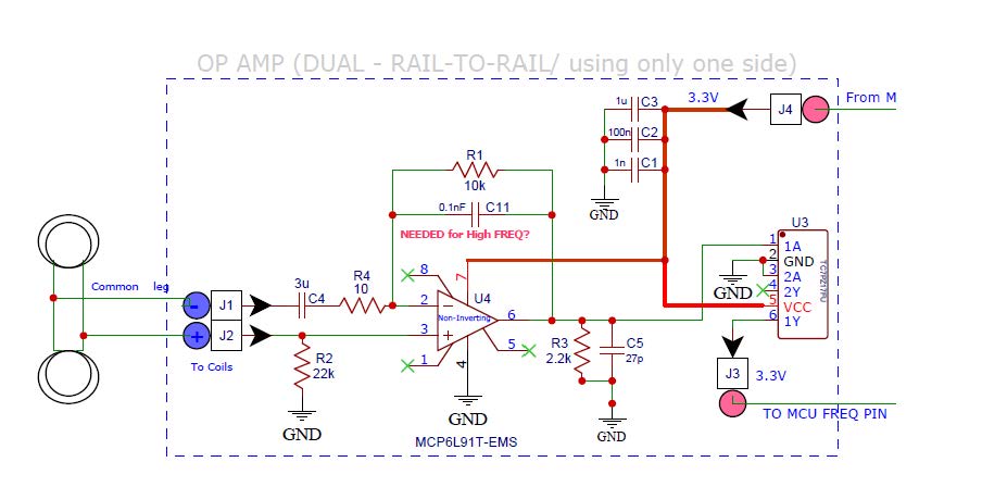
The reluctance-current is generated from two coils by ferrous movement passing through them. The coils are 10 ohm each with 0.254 mH. The current coming out of them is a sine wave that goes positive and negative. The circuit works 95% of the time as it is, but at times it seems that the difference between the two op-amp inputs (2 and 3) is not enough to result in an output.

On the bench, if I simulate things and feed a positive 3 V pulse into J1 going to Pin 2 of the op-amp and also ground J2 (going to pin 3) then it works 100% of the time. Of course, in real life the current is not only positive.

I suspect that when the positive and negative current is generated in the form of a sine wave, at times the input via J2 going into pin 3 of the op-amp overrides J1 going into Pin 2 of the op-amp, thus the op-amp does not put out any amplified signals. Should I change R2 to a lower value like 2-3k, or should I add also a capacitor in series between J2 and pin 3 of the op-amp?

Update: I made a small breadboard with the changes mentioned in the suggested below and jerry-rigged it to the PCB, but was not able to get any reliable readings as the setup was jerry-rigged. I I will recreate the entire OP AMP front-end circuit on a larger breadboard.

Will also consider the suggestions made by @Kartman and @EJE which led me to these links: https://www.reddit.com/r/AskElectronics/comments/71jqlq/variable_reluctance_waveform_op_amp_circuit_issues/ http://www.megamanual.com/ms2/pcb.htm

A comparator may be a better solution, but for now will continue with the OP AMP. I am a bit confused about using the (-) or (+) OP AMP inputs correctly. Any benefits to gain in my case to sue one over the other, besides non-inverting (+) and inverting (-)? For now, I think I will be looking at increasing resistor R4 to around 2k-3k which will still give a 5x gain with R1. A larger R4 value I believe will lead to a larger voltage change. I was concerned that a larger resistor will attenuate the signal generated from the coils by "suppressing" the current.

Also, wondering if I should have the two coils in series (instead of parallel, currently) with on end tied to ground and the other to one OP AMP input? Something like this: enter image description here
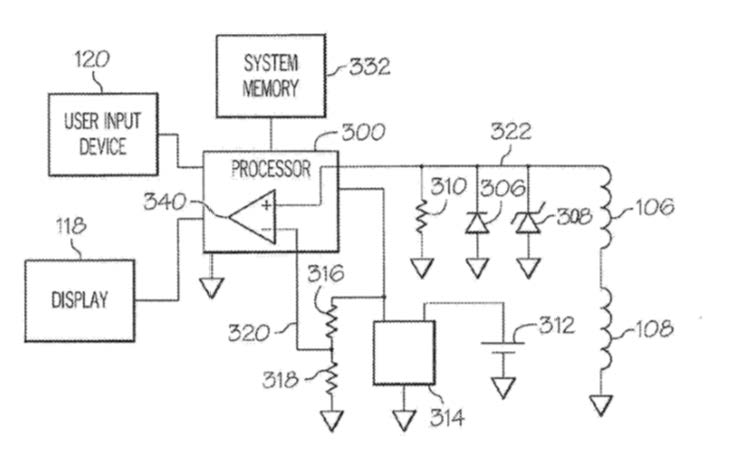
It's a comparator with a 1/2VCC input from voltage divider, and other input from two coils in series with zener and regular diodes and load resistor.

enter image description here

-20mV to +60mV

updated board with DC center added

The problem is only in the input stage of the op-amp.

Edited: removed reference to "eddy-current" and changed to "reluctance".

The reluctance-current is generated from two coils by ferrous movement passing through them. The coils are 10 ohm each with 0.254 mH. The current coming out of them is a sine wave that goes positive and negative. The circuit works 95% of the time as it is, but at times it seems that the difference between the two op-amp inputs (2 and 3) is not enough to result in an output.

On the bench, if I simulate things and feed a positive 3 V pulse into J1 going to Pin 2 of the op-amp and also ground J2 (going to pin 3) then it works 100% of the time. Of course, in real life the current is not only positive.

I suspect that when the positive and negative current is generated in the form of a sine wave, at times the input via J2 going into pin 3 of the op-amp overrides J1 going into Pin 2 of the op-amp, thus the op-amp does not put out any amplified signals. Should I change R2 to a lower value like 2-3k, or should I add also a capacitor in series between J2 and pin 3 of the op-amp?

Update: I made a small breadboard with the changes mentioned in the suggested below and jerry-rigged it to the PCB, but was not able to get any reliable readings as the setup was jerry-rigged. I will recreate the entire OP AMP front-end circuit on a larger breadboard.

Will also consider the suggestions made by @Kartman and @EJE which led me to these links: https://www.reddit.com/r/AskElectronics/comments/71jqlq/variable_reluctance_waveform_op_amp_circuit_issues/ http://www.megamanual.com/ms2/pcb.htm

A comparator may be a better solution, but for now will continue with the OP AMP. I am a bit confused about using the (-) or (+) OP AMP inputs correctly. Any benefits to gain in my case to sue one over the other, besides non-inverting (+) and inverting (-)? For now, I think I will be looking at increasing resistor R4 to around 2k-3k which will still give a 5x gain with R1. A larger R4 value I believe will lead to a larger voltage change. I was concerned that a larger resistor will attenuate the signal generated from the coils by "suppressing" the current.

Also, wondering if I should have the two coils in series (instead of parallel, currently) with on end tied to ground and the other to one OP AMP input? Something like this: enter image description here

It's a comparator with a 1/2VCC input from voltage divider, and other input from two coils in series with zener and regular diodes and load resistor.
enter image description here

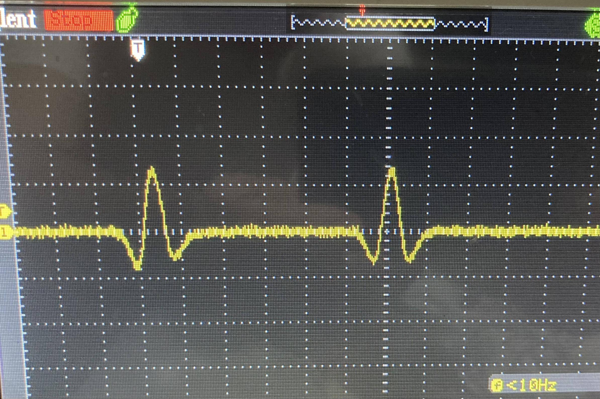
-20mV to +60mV

updated board with DC center added

The problem is only in the input stage of the op-amp.

Edited: removed reference to "eddy-current" and changed to "reluctance".

The reluctance-current is generated from two coils by ferrous movement passing through them. The coils are 10 ohm each with 0.254 mH. The current coming out of them is a sine wave that goes positive and negative. The circuit works 95% of the time as it is, but at times it seems that the difference between the two op-amp inputs (2 and 3) is not enough to result in an output.

On the bench, if I simulate things and feed a positive 3 V pulse into J1 going to Pin 2 of the op-amp and also ground J2 (going to pin 3) then it works 100% of the time. Of course, in real life the current is not only positive.

I suspect that when the positive and negative current is generated in the form of a sine wave, at times the input via J2 going into pin 3 of the op-amp overrides J1 going into Pin 2 of the op-amp, thus the op-amp does not put out any amplified signals. Should I change R2 to a lower value like 2-3k, or should I add also a capacitor in series between J2 and pin 3 of the op-amp?

Update: I made a small breadboard with the changes suggested below and jerry-rigged it to the PCB, but was not able to get any reliable readings. I will recreate the entire OP AMP front-end circuit on a larger breadboard.

Will also consider the suggestions made by @Kartman and @EJE which led me to these links: https://www.reddit.com/r/AskElectronics/comments/71jqlq/variable_reluctance_waveform_op_amp_circuit_issues/ http://www.megamanual.com/ms2/pcb.htm

A comparator may be a better solution, but for now will continue with the OP AMP. I am a bit confused about using the (-) or (+) OP AMP inputs correctly. Any benefits to gain in my case to sue one over the other, besides non-inverting (+) and inverting (-)? For now, I think I will be looking at increasing resistor R4 to around 2k-3k which will still give a 5x gain with R1. A larger R4 value I believe will lead to a larger voltage change. I was concerned that a larger resistor will attenuate the signal generated from the coils by "suppressing" the current.

Also, wondering if I should have the two coils in series (instead of parallel, currently) with on end tied to ground and the other to one OP AMP input? Something like this: enter image description here

It's a comparator with a 1/2VCC input from voltage divider, and other input from two coils in series with zener and regular diodes and load resistor.
enter image description here

-20mV to +60mV

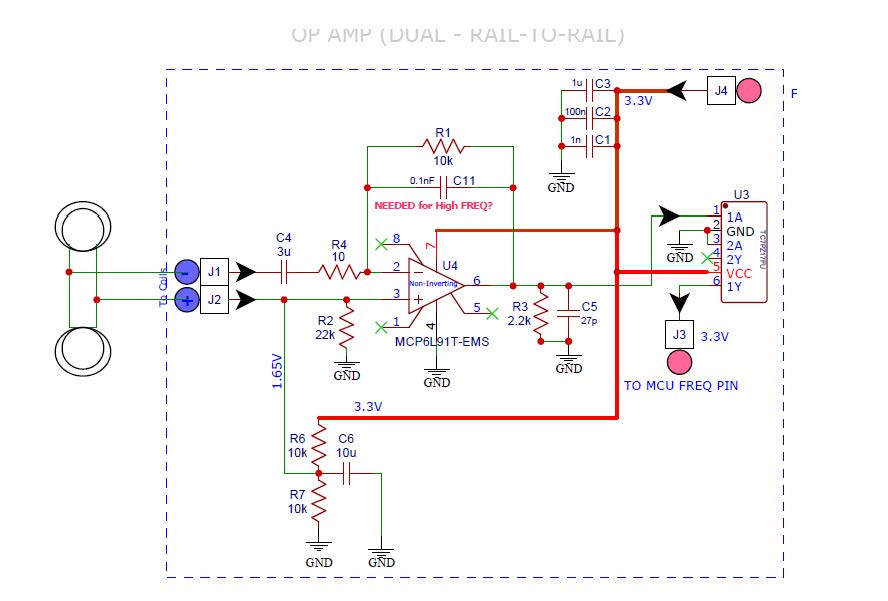
updated board with DC center added

edited body
Source Link
TommyS
  • 135
  • 12

The problem is only in the input stage of the op-amp.

Edited: removed reference to "eddy-current" and changed to "reluctance".

The reluctance-current is generated from two coils by ferrous movement passing through them. The coils are 10 ohm each with 0.254 mH. The current coming out of them is a sine wave that goes positive and negative. The circuit works 95% of the time as it is, but at times it seems that the difference between the two op-amp inputs (2 and 3) is not enough to result in an output.

On the bench, if I simulate things and feed a positive 3 V pulse into J1 going to Pin 2 of the op-amp and also ground J2 (going to pin 3) then it works 100% of the time. Of course, in real life the current is not only positive.

I suspect that when the positive and negative current is generated in the form of a sine wave, at times the input via J2 going into pin 3 of the op-amp overrides J1 going into Pin 2 of the op-amp, thus the op-amp does not put out any amplified signals. Should I change R2 to a lower value like 2-3k, or should I add also a capacitor in series between J2 and pin 3 of the op-amp?

Update: I made a small breadboard with the changes mentioned in the suggested below and jerry-rigged it to the PCB, but was not able to get any reliable readings as the setup was jerry-rigged. I will recreate the entire OP AMP front-end circuit on a larger breadboard.

Will also consider the suggestions made by @Kartman and @EJE which kedled me to these links: https://www.reddit.com/r/AskElectronics/comments/71jqlq/variable_reluctance_waveform_op_amp_circuit_issues/ http://www.megamanual.com/ms2/pcb.htm

A comparator may be a better solution, but for now will continue with the OP AMP. I am a bit confused about using the (-) or (+) OP AMP inputs correctly. Any benefits to gain in my case to sue one over the other, besides non-inverting (+) and inverting (-)? For now, I think I will be looking at increasing resistor R4 to around 2k-3k which will still give a 5x gain with R1. A larger R4 value I believe will lead to a larger voltage change. I was concerned that a larger resistor will attenuate the signal generated from the coils by "suppressing" the current.

Also, wondering if I should have the two coils in series (instead of parallel, currently) with on end tied to ground and the other to one OP AMP input? Something like this: enter image description here

It's a comparator with a 1/2VCC input from voltage divider, and other input from two coils in series with zener and regular diodes and load resistor.

enter image description here

-20mV to +60mV

updated board with DC center added

The problem is only in the input stage of the op-amp.

Edited: removed reference to "eddy-current" and changed to "reluctance".

The reluctance-current is generated from two coils by ferrous movement passing through them. The coils are 10 ohm each with 0.254 mH. The current coming out of them is a sine wave that goes positive and negative. The circuit works 95% of the time as it is, but at times it seems that the difference between the two op-amp inputs (2 and 3) is not enough to result in an output.

On the bench, if I simulate things and feed a positive 3 V pulse into J1 going to Pin 2 of the op-amp and also ground J2 (going to pin 3) then it works 100% of the time. Of course, in real life the current is not only positive.

I suspect that when the positive and negative current is generated in the form of a sine wave, at times the input via J2 going into pin 3 of the op-amp overrides J1 going into Pin 2 of the op-amp, thus the op-amp does not put out any amplified signals. Should I change R2 to a lower value like 2-3k, or should I add also a capacitor in series between J2 and pin 3 of the op-amp?

Update: I made a small breadboard with the changes mentioned in the suggested below and jerry-rigged it to the PCB, but was not able to get any reliable readings as the setup was jerry-rigged. I will recreate the entire OP AMP front-end circuit on a larger breadboard.

Will also consider the suggestions made by @Kartman and @EJE which ked me to these links: https://www.reddit.com/r/AskElectronics/comments/71jqlq/variable_reluctance_waveform_op_amp_circuit_issues/ http://www.megamanual.com/ms2/pcb.htm

A comparator may be a better solution, but for now will continue with the OP AMP. I am a bit confused about using the (-) or (+) OP AMP inputs correctly. Any benefits to gain in my case to sue one over the other, besides non-inverting (+) and inverting (-)? For now, I think I will be looking at increasing resistor R4 to around 2k-3k which will still give a 5x gain with R1. A larger R4 value I believe will lead to a larger voltage change. I was concerned that a larger resistor will attenuate the signal generated from the coils by "suppressing" the current.

Also, wondering if I should have the two coils in series (instead of parallel, currently) with on end tied to ground and the other to one OP AMP input? Something like this: enter image description here

It's a comparator with a 1/2VCC input from voltage divider, and other input from two coils in series with zener and regular diodes and load resistor.

enter image description here

-20mV to +60mV

updated board with DC center added

The problem is only in the input stage of the op-amp.

Edited: removed reference to "eddy-current" and changed to "reluctance".

The reluctance-current is generated from two coils by ferrous movement passing through them. The coils are 10 ohm each with 0.254 mH. The current coming out of them is a sine wave that goes positive and negative. The circuit works 95% of the time as it is, but at times it seems that the difference between the two op-amp inputs (2 and 3) is not enough to result in an output.

On the bench, if I simulate things and feed a positive 3 V pulse into J1 going to Pin 2 of the op-amp and also ground J2 (going to pin 3) then it works 100% of the time. Of course, in real life the current is not only positive.

I suspect that when the positive and negative current is generated in the form of a sine wave, at times the input via J2 going into pin 3 of the op-amp overrides J1 going into Pin 2 of the op-amp, thus the op-amp does not put out any amplified signals. Should I change R2 to a lower value like 2-3k, or should I add also a capacitor in series between J2 and pin 3 of the op-amp?

Update: I made a small breadboard with the changes mentioned in the suggested below and jerry-rigged it to the PCB, but was not able to get any reliable readings as the setup was jerry-rigged. I will recreate the entire OP AMP front-end circuit on a larger breadboard.

Will also consider the suggestions made by @Kartman and @EJE which led me to these links: https://www.reddit.com/r/AskElectronics/comments/71jqlq/variable_reluctance_waveform_op_amp_circuit_issues/ http://www.megamanual.com/ms2/pcb.htm

A comparator may be a better solution, but for now will continue with the OP AMP. I am a bit confused about using the (-) or (+) OP AMP inputs correctly. Any benefits to gain in my case to sue one over the other, besides non-inverting (+) and inverting (-)? For now, I think I will be looking at increasing resistor R4 to around 2k-3k which will still give a 5x gain with R1. A larger R4 value I believe will lead to a larger voltage change. I was concerned that a larger resistor will attenuate the signal generated from the coils by "suppressing" the current.

Also, wondering if I should have the two coils in series (instead of parallel, currently) with on end tied to ground and the other to one OP AMP input? Something like this: enter image description here

It's a comparator with a 1/2VCC input from voltage divider, and other input from two coils in series with zener and regular diodes and load resistor.

enter image description here

-20mV to +60mV

updated board with DC center added

added 1390 characters in body
Source Link
TommyS
  • 135
  • 12

The problem is only in the input stage of the op-amp.

Edited: removed reference to "eddy-current" and changed to "reluctance".

The reluctance-current is generated from two coils by ferrous movement passing through them. The coils are 10 ohm each with 0.254 mH. The current coming out of them is a sine wave that goes positive and negative. The circuit works 95% of the time as it is, but at times it seems that the difference between the two op-amp inputs (2 and 3) is not enough to result in an output.

On the bench, if I simulate things and feed a positive 3 V pulse into J1 going to Pin 2 of the op-amp and also ground J2 (going to pin 3) then it works 100% of the time. Of course, in real life the current is not only positive.

I suspect that when the positive and negative current is generated in the form of a sine wave, at times the input via J2 going into pin 3 of the op-amp overrides J1 going into Pin 2 of the op-amp, thus the op-amp does not put out any amplified signals. Should I change R2 to a lower value like 2-3k, or should I add also a capacitor in series between J2 and pin 3 of the op-amp?

Update: I made a small breadboard with the changes mentioned in the suggested below and jerry-rigged it to the PCB, but was not able to get any reliable readings as the setup was jerry-rigged. I will recreate the entire OP AMP front-end circuit on a larger breadboard.

Will also consider the suggestions made by @Kartman and @EJE which ked me to these links: https://www.reddit.com/r/AskElectronics/comments/71jqlq/variable_reluctance_waveform_op_amp_circuit_issues/ http://www.megamanual.com/ms2/pcb.htm

A comparator may be a better solution, but for now will continue with the OP AMP. I am a bit confused about using the (-) or (+) OP AMP inputs correctly. Any benefits to gain in my case to sue one over the other, besides non-inverting (+) and inverting (-)? For now, I think I will be looking at increasing resistor R4 to around 2k-3k which will still give a 5x gain with R1. A larger R4 value I believe will lead to a larger voltage change. I was concerned that a larger resistor will attenuate the signal generated from the coils by "suppressing" the current.

Also, wondering if I should have the two coils in series (instead of parallel, currently) with on end tied to ground and the other to one OP AMP input? Something like this: enter image description here

It's a comparator with a 1/2VCC input from voltage divider, and other input from two coils in series with zener and regular diodes and load resistor.

enter image description here

-20mV to +60mV

updated board with DC center added

The problem is only in the input stage of the op-amp.

Edited: removed reference to "eddy-current" and changed to "reluctance".

The reluctance-current is generated from two coils by ferrous movement passing through them. The coils are 10 ohm each with 0.254 mH. The current coming out of them is a sine wave that goes positive and negative. The circuit works 95% of the time as it is, but at times it seems that the difference between the two op-amp inputs (2 and 3) is not enough to result in an output.

On the bench, if I simulate things and feed a positive 3 V pulse into J1 going to Pin 2 of the op-amp and also ground J2 (going to pin 3) then it works 100% of the time. Of course, in real life the current is not only positive.

I suspect that when the positive and negative current is generated in the form of a sine wave, at times the input via J2 going into pin 3 of the op-amp overrides J1 going into Pin 2 of the op-amp, thus the op-amp does not put out any amplified signals. Should I change R2 to a lower value like 2-3k, or should I add also a capacitor in series between J2 and pin 3 of the op-amp?

Update: I made a small breadboard with the changes mentioned in the suggested below and jerry-rigged it to the PCB, but was not able to get any reliable readings as the setup was jerry-rigged. I will recreate the entire OP AMP front-end circuit on a larger breadboard.

Will also consider the suggestions made by @Kartman and @EJE which ked me to these links: https://www.reddit.com/r/AskElectronics/comments/71jqlq/variable_reluctance_waveform_op_amp_circuit_issues/ http://www.megamanual.com/ms2/pcb.htm

A comparator may be a better solution, but for now will continue with the OP AMP. I am a bit confused about using the (-) or (+) OP AMP inputs correctly. Any benefits to gain in my case to sue one over the other, besides non-inverting (+) and inverting (-)? For now, I think I will be looking at increasing resistor R4 to around 2k-3k which will still give a 5x gain with R1. A larger R4 value I believe will lead to a larger voltage change. I was concerned that a larger resistor will attenuate the signal generated from the coils by "suppressing" the current.

Also, wondering if I should have the two coils in series (instead of parallel, currently) with on end tied to ground and the other to one OP AMP input? Something like this: enter image description here

It's a comparator with a 1/2VCC input from voltage divider, and other input from two coils in series with zener and regular diodes and load resistor.

enter image description here

-20mV to +60mV

updated board with DC center added

added 71 characters in body
Source Link
TommyS
  • 135
  • 12
Loading
added 95 characters in body
Source Link
TommyS
  • 135
  • 12
Loading
K = Kelvin. k = kilo.
Source Link
winny
  • 16.8k
  • 6
  • 50
  • 71
Loading
deleted 5 characters in body; edited title
Source Link
JRE
  • 73.5k
  • 10
  • 112
  • 194
Loading
deleted 11 characters in body; edited title
Source Link
TommyS
  • 135
  • 12
Loading
deleted 18 characters in body
Source Link
TommyS
  • 135
  • 12
Loading
added 130 characters in body
Source Link
Antonio51
  • 15.7k
  • 1
  • 9
  • 25
Loading
added 89 characters in body
Source Link
TommyS
  • 135
  • 12
Loading
Source Link
TommyS
  • 135
  • 12
Loading