added 4 characters in body; edited title
Source Link
ocrdu
  • 9.3k
  • 23
  • 32
  • 42

Analog Step Sequencer Schematic Helpstep sequencer schematic help

I'm currently working on an analog step sequencer for a synthesizer I'm making. It has a split rail 24V24 V supply (so +12V, gndGND, -12V) and follows the Kosmo specification. The features I want are:

  • 8 steps with both gate and variable voltage outputs
  • LEDs showing step progression, as well as output LED showing gate sequence
  • Clock and Resetreset inputs
  • Internal clock generator with variable pulse width

The design is mostly based off of Moritz Klein's 5 step sequencer design, the video demonstrating it is here. However, I've changed it to 8 steps instead of 5 and I've added an internal clock generator.

If there are any issues with this, it's most likely in the clock generator section. This is based off of this article about using a 555 timer as a sawtooth wave generator. I've added a potentiometer to modulate the frequency, and I'm using a pair of opampsop-amps to buffer and then compare the output to a static value to turn it into a pulse wave. By changing the offset value the pulse width should change.

If you can see any issues in this design, please let me know!. I'm trying to make this work as well as possible.   

step sequencer schematic

Analog Step Sequencer Schematic Help

I'm currently working on an analog step sequencer for a synthesizer I'm making. It has a split rail 24V supply (so +12V, gnd, -12V) and follows the Kosmo specification. The features I want are:

  • 8 steps with both gate and variable voltage outputs
  • LEDs showing step progression, as well as output LED showing gate sequence
  • Clock and Reset inputs
  • Internal clock generator with variable pulse width

The design is mostly based off of Moritz Klein's 5 step sequencer design, the video demonstrating it is here. However, I've changed it to 8 steps instead of 5 and I've added an internal clock generator.

If there are any issues with this, it's most likely in the clock generator section. This is based off of this article about using a 555 timer as a sawtooth wave generator. I've added a potentiometer to modulate the frequency, and I'm using a pair of opamps to buffer and then compare the output to a static value to turn it into a pulse wave. By changing the offset value the pulse width should change.

If you can see any issues in this design, please let me know! I'm trying to make this work as well as possible.  step sequencer schematic
Analog step sequencer schematic help

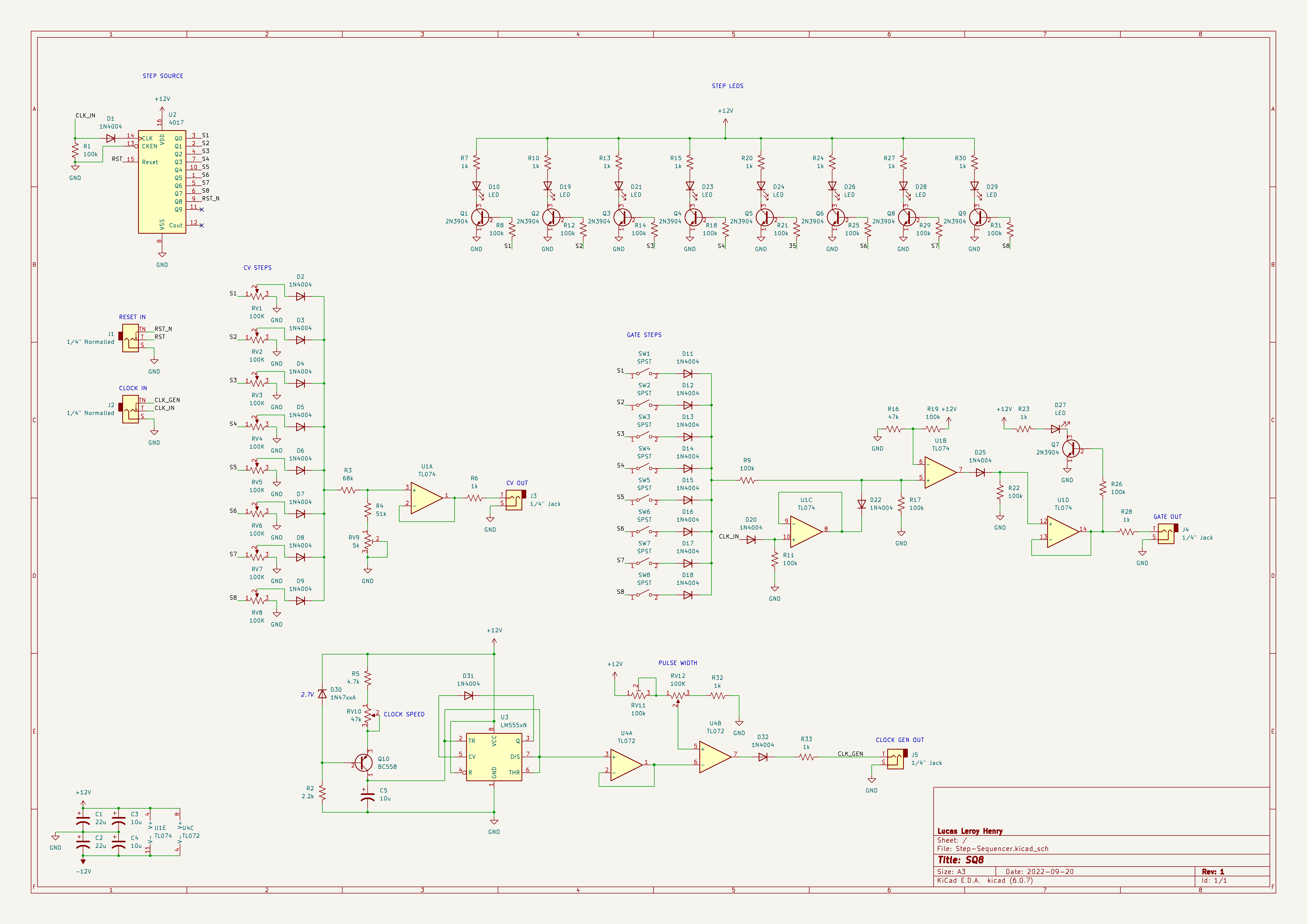
I'm currently working on an analog step sequencer for a synthesizer I'm making. It has a split rail 24 V supply (so +12V, GND, -12V) and follows the Kosmo specification. The features I want are:

  • 8 steps with both gate and variable voltage outputs
  • LEDs showing step progression, as well as output LED showing gate sequence
  • Clock and reset inputs
  • Internal clock generator with variable pulse width

The design is mostly based off of Moritz Klein's 5 step sequencer design, the video demonstrating it is here. However, I've changed it to 8 steps instead of 5 and I've added an internal clock generator.

If there are any issues with this, it's most likely in the clock generator section. This is based off of this article about using a 555 timer as a sawtooth wave generator. I've added a potentiometer to modulate the frequency, and I'm using a pair of op-amps to buffer and then compare the output to a static value to turn it into a pulse wave. By changing the offset value the pulse width should change.

If you can see any issues in this design, please let me know. I'm trying to make this work as well as possible. 

step sequencer schematic

Source Link

Analog Step Sequencer Schematic Help

I'm currently working on an analog step sequencer for a synthesizer I'm making. It has a split rail 24V supply (so +12V, gnd, -12V) and follows the Kosmo specification. The features I want are:

  • 8 steps with both gate and variable voltage outputs
  • LEDs showing step progression, as well as output LED showing gate sequence
  • Clock and Reset inputs
  • Internal clock generator with variable pulse width

The design is mostly based off of Moritz Klein's 5 step sequencer design, the video demonstrating it is here. However, I've changed it to 8 steps instead of 5 and I've added an internal clock generator.

If there are any issues with this, it's most likely in the clock generator section. This is based off of this article about using a 555 timer as a sawtooth wave generator. I've added a potentiometer to modulate the frequency, and I'm using a pair of opamps to buffer and then compare the output to a static value to turn it into a pulse wave. By changing the offset value the pulse width should change.

If you can see any issues in this design, please let me know! I'm trying to make this work as well as possible. step sequencer schematic