added 114 characters in body
Source Link
jonathanjo
  • 16.2k
  • 3
  • 36
  • 74

Warning about mains voltages: do not attempt any of this if you're not competent with mains (120/220 VAC) voltages, which will kill you if you make a mistake.

The textbook circuit for driving a relay with a transistor is the following, Circuit A p821 of The Art of Electronics, 3rd ed, Horowitz and Hill, one of the most influential textbooks. This transistor is a "low side switch", ie, it performs a switching action on the low-voltage side of the load: "a switch to ground".

The input gate is your PIR sensor; the load is your relay and its diode. You can use a huge range of NPN transistors in this position, including the BC547 you mention, and also the extremely common 2n2222. The resistor of 1K shown in the example depends on the PIR sensor, which we don't know much about, and the relay current, which we don't know either. The purpose of the resistor is to limit the current into the base; took much and the transistor will break. Similarly, the purpose of the diodethe diode is to protect the transistor when the relay goes off and discharges its energy backwards.

The best way to find out the right resistor is to post the specifications of your relay (the critical parameter is the voltage and resistance of the coil) and at least the voltage output of the PIR detector.

enter image description here

You might build it as follows. At the risk of sounding obvious: you test the relay portion works exactly how you want it before going anywhere near the mains voltage.
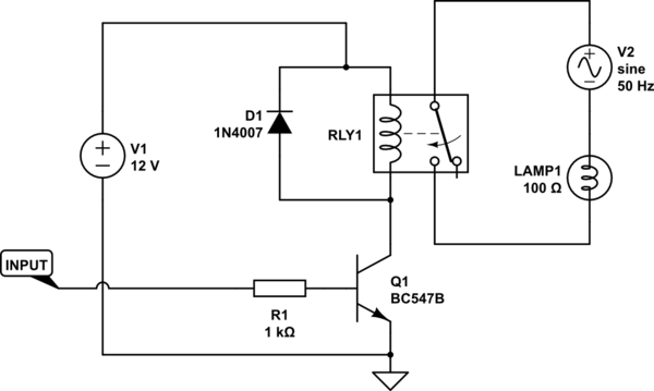
schematic

simulate this circuit – Schematic created using CircuitLab

Warning about mains voltages: do not attempt any of this if you're not competent with mains (120/220 VAC) voltages, which will kill you if you make a mistake.

The textbook circuit for driving a relay with a transistor is the following, Circuit A p821 of The Art of Electronics, 3rd ed, Horowitz and Hill, one of the most influential textbooks. This transistor is a "low side switch", ie, it performs a switching action on the low-voltage side of the load: "a switch to ground".

The input gate is your PIR sensor; the load is your relay and its diode. You can use a huge range of NPN transistors in this position, including the BC547 you mention, and also the extremely common 2n2222. The resistor of 1K shown in the example depends on the PIR sensor, which we don't know much about, and the relay current, which we don't know either. The purpose of the resistor is to limit the current into the base; took much and the transistor will break. Similarly, the purpose of the diode is to protect the transistor when the relay goes off and discharges its energy backwards.

The best way to find out the right resistor is to post the specifications of your relay (the critical parameter is the voltage and resistance of the coil) and at least the voltage output of the PIR detector.

enter image description here

You might build it as follows. At the risk of sounding obvious: you test the relay portion works exactly how you want it before going anywhere near the mains voltage.

schematic

simulate this circuit – Schematic created using CircuitLab
Warning about mains voltages: do not attempt any of this if you're not competent with mains (120/220 VAC) voltages, which will kill you if you make a mistake.

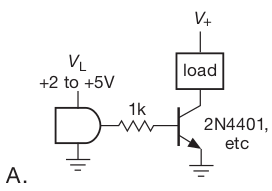
The textbook circuit for driving a relay with a transistor is the following, Circuit A p821 of The Art of Electronics, 3rd ed, Horowitz and Hill, one of the most influential textbooks. This transistor is a "low side switch", ie, it performs a switching action on the low-voltage side of the load: "a switch to ground".

The input gate is your PIR sensor; the load is your relay and its diode. You can use a huge range of NPN transistors in this position, including the BC547 you mention, and also the extremely common 2n2222. The resistor of 1K shown in the example depends on the PIR sensor, which we don't know much about, and the relay current, which we don't know either. The purpose of the resistor is to limit the current into the base; took much and the transistor will break. Similarly, the purpose of the diode is to protect the transistor when the relay goes off and discharges its energy backwards.

The best way to find out the right resistor is to post the specifications of your relay (the critical parameter is the voltage and resistance of the coil) and at least the voltage output of the PIR detector.

enter image description here

You might build it as follows. At the risk of sounding obvious: you test the relay portion works exactly how you want it before going anywhere near the mains voltage.

schematic

simulate this circuit – Schematic created using CircuitLab

added 498 characters in body
Source Link
jonathanjo
  • 16.2k
  • 3
  • 36
  • 74

Warning about mains voltages: do not attempt any of this if you're not competent with mains (120/220 VAC) voltages, which will kill you if you make a mistake.

The textbook circuit for driving a relay with a transistor is the following, Circuit A p821 of The Art of Electronics, 3rd ed, Horowitz and Hill, one of the most influential textbooks. This transistor is a "low side switch", ie, it performs a switching action on the low-voltage side of the load: "a switch to ground".

The input gate is your PIR sensor; the load is your relay and its diode. You can use a huge range of NPN transistors in this position, including the BC547 you mention, and also the extremely common 2n2222. The resistor of 1K shown in the example depends on the PIR sensor, which we don't know much about, and the relay current, which we don't know either. The purpose of the resistor is to limit the current into the base; took much and the transistor will break. Similarly, the purpose of the diode is to protect the transistor when the relay goes off and discharges its energy backwards.

The best way to find out the right resistor is to post the specifications of your relay (the critical parameter is the voltage and resistance of the coil) and at least the voltage output of the PIR detector.

enter image description here

You might build it as follows. At the risk of sounding obvious: you test the relay portion works exactly how you want it before going anywhere near the mains voltage.

schematic

simulate this circuit – Schematic created using CircuitLab

Warning about mains voltages: do not attempt any of this if you're not competent with mains (120/220 VAC) voltages, which will kill you if you make a mistake.

The textbook circuit for driving a relay with a transistor is the following, Circuit A p821 of The Art of Electronics, 3rd ed, Horowitz and Hill, one of the most influential textbooks. This transistor is a "low side switch", ie, it performs a switching action on the low-voltage side of the load: "a switch to ground".

The input gate is your PIR sensor; the load is your relay and its diode. You can use a huge range of NPN transistors in this position, including the BC547 you mention, and also the extremely common 2n2222. The resistor of 1K shown in the example depends on the PIR sensor, which we don't know much about.

enter image description here

You might build it as follows. At the risk of sounding obvious: you test the relay portion works exactly how you want it before going anywhere near the mains voltage.

schematic

simulate this circuit – Schematic created using CircuitLab

Warning about mains voltages: do not attempt any of this if you're not competent with mains (120/220 VAC) voltages, which will kill you if you make a mistake.

The textbook circuit for driving a relay with a transistor is the following, Circuit A p821 of The Art of Electronics, 3rd ed, Horowitz and Hill, one of the most influential textbooks. This transistor is a "low side switch", ie, it performs a switching action on the low-voltage side of the load: "a switch to ground".

The input gate is your PIR sensor; the load is your relay and its diode. You can use a huge range of NPN transistors in this position, including the BC547 you mention, and also the extremely common 2n2222. The resistor of 1K shown in the example depends on the PIR sensor, which we don't know much about, and the relay current, which we don't know either. The purpose of the resistor is to limit the current into the base; took much and the transistor will break. Similarly, the purpose of the diode is to protect the transistor when the relay goes off and discharges its energy backwards.

The best way to find out the right resistor is to post the specifications of your relay (the critical parameter is the voltage and resistance of the coil) and at least the voltage output of the PIR detector.

enter image description here

You might build it as follows. At the risk of sounding obvious: you test the relay portion works exactly how you want it before going anywhere near the mains voltage.

schematic

simulate this circuit – Schematic created using CircuitLab

added 322 characters in body
Source Link
jonathanjo
  • 16.2k
  • 3
  • 36
  • 74

Warning about mains voltages: do not attempt any of this if you're not competent with mains (120/220 VAC) voltages, which will kill you if you make a mistake.

The textbook circuit for driving a relay with a transistor is the following, Circuit A p821 of The Art of Electronics, 3rd ed, Horowitz and Hill, one of the most influential textbooks. This transistor is a "low side switch", ie, it performs a switching action on the low-voltage side of the load: "a switch to ground".

The input gate is your PIR sensor; the load is your relay and its diode. You can use a huge range of NPN transistors in this position, including the BC547 you mention, and also the extremely common 2n2222. The resistor of 1K shown in the example depends on the PIR sensor, which we don't know much about.

enter image description here

You might build it as follows. At the risk of sounding obvious: you test the relay portion works exactly how you want it before going anywhere near the mains voltage.

schematic

simulate this circuit – Schematic created using CircuitLab

The textbook circuit for driving a relay with a transistor is the following, Circuit A p821 of The Art of Electronics, 3rd ed, Horowitz and Hill, one of the most influential textbooks. This transistor is a "low side switch", ie, it performs a switching action on the low-voltage side of the load: "a switch to ground".

The input gate is your PIR sensor; the load is your relay and its diode. You can use a huge range of NPN transistors in this position, including the BC547 you mention, and also the extremely common 2n2222. The resistor of 1K shown in the example depends on the PIR sensor, which we don't know much about.

enter image description here

You might build it as follows.

schematic

simulate this circuit – Schematic created using CircuitLab

Warning about mains voltages: do not attempt any of this if you're not competent with mains (120/220 VAC) voltages, which will kill you if you make a mistake.

The textbook circuit for driving a relay with a transistor is the following, Circuit A p821 of The Art of Electronics, 3rd ed, Horowitz and Hill, one of the most influential textbooks. This transistor is a "low side switch", ie, it performs a switching action on the low-voltage side of the load: "a switch to ground".

The input gate is your PIR sensor; the load is your relay and its diode. You can use a huge range of NPN transistors in this position, including the BC547 you mention, and also the extremely common 2n2222. The resistor of 1K shown in the example depends on the PIR sensor, which we don't know much about.

enter image description here

You might build it as follows. At the risk of sounding obvious: you test the relay portion works exactly how you want it before going anywhere near the mains voltage.

schematic

simulate this circuit – Schematic created using CircuitLab

added 322 characters in body
Source Link
jonathanjo
  • 16.2k
  • 3
  • 36
  • 74
Loading
added 322 characters in body
Source Link
jonathanjo
  • 16.2k
  • 3
  • 36
  • 74
Loading
Source Link
jonathanjo
  • 16.2k
  • 3
  • 36
  • 74
Loading