Building a conceptual circuit
I will reveal the idea behind this clever circuit solution in five consecutive steps. Each step is illustrated by a picture consisting of two parts - a hydraulic analogy is shown on the left and its corresponding electrical circuit on the right.
1. Input quantity. The charge amplifier is designed to amplify signals from piezoelectric sensors. They are fully capacitive and have the behavior of a charged capacitor C1 with charge Q1 and voltage VC1 (Fig. 1b) whose hydraulic analogy is a vessel full of water with volume VH1 and height H1 (Fig. 1a).
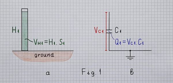
Fig. 1. Hydraulic analogy of а full vessel (a); charged capacitor (b)
So, the voltage across the capacitor (sensor) can serve as an input quantity... and we can think of the piezoelectric sensor of as a voltage source. It cannot be directly applied to a low-resistive load since it will be quickly discharged; it is usually buffered by some kind of a voltage follower.
2. Problems. Only, the stray capacitances between the cables and ground shunt the sensor; they are also charged and an error is introduced. They are charged because there is a voltage; they will be not charged if the input voltage across the capacitor would be zero... but we need it... so it cannot be zero. How do we solve this contradiction?
Maybe the hydraulic analogy can help as? What do they do in industry when it is impossible to measure directly the liquid level in a tank? They use "communicating vessels" - Fig. 2a.
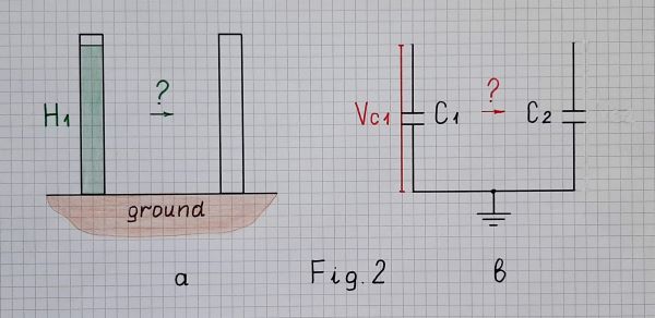
Fig. 2. How do we measure the level of water (a)... and the voltage of the capacitor (b)?
3. Trying to solve the problem. So, the powerful idea is to copy the voltage of the first capacitor C1 to another capacitor C2 and then to measure the voltage VC2 across the second capacitor. And since we want the voltage across the first capacitor to be zero, we should move the charge from the first capacitor to the second one. Let's do it - connect C1 to C2 (Fig. 3b); in the hydraulic analogy, connect the two vessels by a pipe - Fig. 3a.
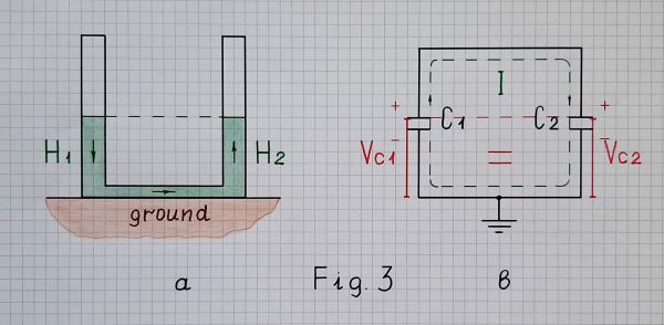
Fig. 3. Measuring the level of water (a) and the voltage of the first capacitor (b) by copying at the end of charge redistribution
To transfer all the charge, current must flow the whole time. In order for current to flow, there must be a difference between the two voltages. So the voltage of the initially charged capacitor C1 must always be higher than the voltage of the charging capacitor C2.
But when connecting the charged capacitor C1 to the empty C2, only half of the charge moves from C1 to C2 (suppose C1 = C2) and the voltage reduces double; after that the current stops flowing (see Two capacitor paradox). What should we do to make the rest of the charge in C1 go to C2?
4. The clever idea. In the hydraulic analogy, we must make sure that the water level in the right vessel is always lower than that of the left. And here we just have to guess that the vessels may be movable (if we connect them with a flexible hose). There are two options - to raise the left vessel or to lower the right vessel. Let's choose the second one because it will lead us to the desired circuit. So, we can start lowering the right vessel so that the water level in it is always zero (Fig. 4a)... like a kind of a "bottomless vessel".
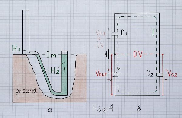
Fig. 4. Compensating the level of water (a) and the voltage of the second capacitor (b) at the end of charge redistribution
Similarly, in the electrical circuit (Fig. 4b), we can begin "moving down" VC2 by the help of a following negative voltage source VOUT. It copies the voltage across C2 and adds this voltage (VC2) to VC1 in a series manner (according to KVL when travelling the loop). Note I have drawn the two voltage sources (VC1 and VOUT) one below the other to show that they are connected in series and in one direction so that their voltages are added (like a battery of two cells).
As a result of applying this clever trick, VC2 is neutralized; the combination of C2 and VOUT behaves as a "virtual piece of wire" with zero voltage... and C1 is "virtually shorted". As a result, all the charge will move to C2. There is no charge in C1... there is no voltage across it...
The same trick is used in all kinds of op-amp inverting circuits with negative feedback where the op-amp output voltage compensates the voltage drop across the second element (R2, C, L, D, etc.) by adding the same voltage in series. It is further developed in circuits with S-shaped true negative resistance (VNIC converters) by adding a multiplied voltage. This is a great idea... the Miller's idea.
5. Implementation. So, this idea can be implemented by a simple electrical arrangement of three elements in a loop - C1, C2 and VOUT (Fig. 5a). In this conceptual electrical circuit, VOUT is a variable voltage source that follows VC2. In contrast to the "geometrically drawn" pictures above, here I have not drawn a reference point (ground) to show that it is not absolutely necessary for the conceptual circuit.
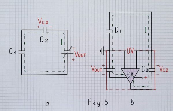
Fig. 5. Conceptual electrical circuit diagram (a) and electronic circuit of a charge amplifier (b) at the end of charge redistribution (draft)
Drawn in such a neat way, Fig. 5a can give us the simplest explanation of the circuit:
We have two capacitors in series - the one is full (charged) to a voltage V and the other is empty (discharged)... and we want to move the charge from the full capacitor to the empty one. For this purpose, we connect another voltage source with the same voltage V in series and in the same direction. The two voltages are added and the same current I begins flowing through both capacitors. As a result, the full capacitor begins discharging and the empty capacitor charging (the charge exits the first and enters the second capacitor). Finally, the first capacitor is fully discharged (empty) and the second capacitor is fully charged (full) to the input voltage V. The current stops flowing... and all the charge of the first capacitor is transferred to the second capacitor.
Briefly, to "drive away" the charge from C1 to C2, connect a source with voltage VC1 in series and in the same direction.
Indeed, our case is a little more sophisticated - the additional voltage is not constant but gradually increasing. It follows the voltage across the second capacitor and, at the end of the process, it is maximum.
Note that if the second capacitor has smaller capacitance, it will charge to a higher voltage... and we will get an amplifier (the hydraulic analogy can also explain this trick). The gain of this "electrical charge ampifier" will be C1/C2.
Now it remains only to replace VOUT with an op-amp so that to make it follow VC2... and we obtain the electronic circuit of an "ideal" charge amplifier - Fig. 5b.
So, what does it amplify?
From all these considerations, we can conclude that the charge amplifier, like any amplifier, ultimately amplifies voltage... the voltage across the input capacitor which is proportional to the charge inside it. Only, for some reasons considered above, it amplifies not the very input voltage but a copy of this voltage created across another capacitor by transferring the charge. More precisely speaking, the "amplification" is obtained by changing the ratio C1/C2... and the op-amp only follows the voltage across C2.
In this DC application, the input source is simply a charged capacitor that can be considered as a kind of "exhausting voltage source"(see Fig. 6 below as an example). Only in AC applications (e.g., the vibrometer shown in Fig. 7), it can be thought of as an "exhausting current source" (a voltage source with significant capacitive internal impedance). That is why, in this case, a piezoelectric sensor can be emulated by a sine wave signal generator with a capacitor in series to its output.
Real charge amplifier
Resistor in parallel. In real op-amp circuits, we have to provide paths for the op-amp input bias currents. In this fully capacitive circuit there is no path for the bias current of the inverting input. The usual solution is to connect a resistor with very high resistance (typically 1 G) in parallel to C2. Thus, in regard to DC, the circuit is a follower with zero input voltage (of the ground).
So the circuit diagram of a real charge amplifier is more complex. Here is an AD example where the charge amplifier is driven by a piezoelectric shock sensor accelerometer:
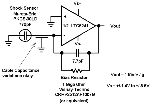
Fig. 6. A real charge amplifier
Resistor in series. To connect two voltage sources (charged capacitors) in parallel is a bad idea since a conflict appears and the current should be infinite... but exactly this arrangement is here. The usual solution to "soften" the conflict is to connect a resistor with a relatively low resistance in series to the input. The same problem appears in the op-amp differentiator; usually, they explain it by an enormously increased gain. Such a more sophisticated version was used in Brüel & Kjær’s vibrometers in the 80s:
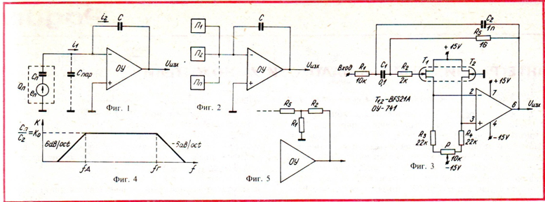
Fig. 7. A more sophisticated real charge amplifier (‘Radio and TV’ BG magazine, August, 1983)
Conclusion
By applying a few basic didactic principles, the basic idea behind this fully capacitive circuit is revealed: measuring indirectly the voltage across a charged input capacitor (sensor) by moving (redistributing) the charge to another capacitor. For this purpose, the input capacitor is discharged through the output capacitor whose voltage is compensated by an equivalent voltage in series... and the compensating voltage is used as an output voltage.
The benefits of this solution are that input stray capacitances are shorted, the output voltage is buffered and it can be amplified by simply changing the ratio C1/C2.


