edited body
Source Link

I have designed a BUCK converter circuit using UC3843. Here is the DATASHEET FIG1.
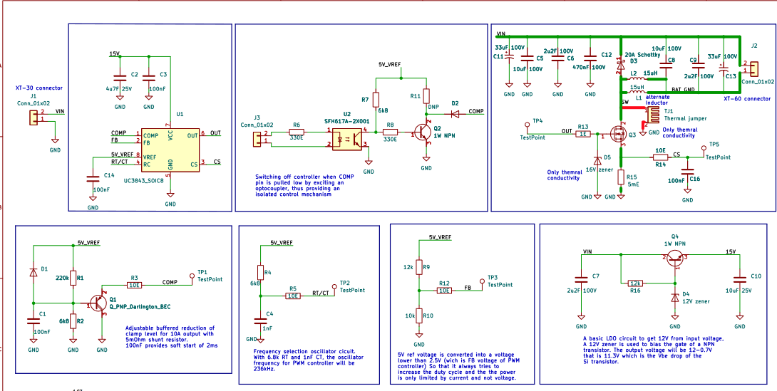
You can find the circuit diagram above. I want to limit the current to 10A and accordingly I have designed the external compensation circuit.

But, If I probe the Output pin of the IC, I am not getting any PWM output. So I started debugging and removed R3 to not have compensation in the circuit to just basically check the functionality of the IC as a PWM controller. But still there was nothing at the output pin.

I have testpoints for all the IC pins on the PCB. SO, I wanted to chackcheck the voltage on RC pin on the IC and as soon as I touch only one probe of multimeter with the Test point, the PWM output was being generated. If I am guessing correctly, my multimeter probe is adding some parasitic component to the RC pin which is making it generate PWM signal at OUTPUT pi of IC.

Can you tell me why I am experiencing this behaviour with this IC and how to fix it?

I have designed a BUCK converter circuit using UC3843. Here is the DATASHEET FIG1.

You can find the circuit diagram above. I want to limit the current to 10A and accordingly I have designed the external compensation circuit.

But, If I probe the Output pin of the IC, I am not getting any PWM output. So I started debugging and removed R3 to not have compensation in the circuit to just basically check the functionality of the IC as a PWM controller. But still there was nothing at the output pin.

I have testpoints for all the IC pins on the PCB. SO, I wanted to chack the voltage on RC pin on the IC and as soon as I touch only one probe of multimeter with the Test point, the PWM output was being generated. If I am guessing correctly, my multimeter probe is adding some parasitic component to the RC pin which is making it generate PWM signal at OUTPUT pi of IC.

Can you tell me why I am experiencing this behaviour with this IC and how to fix it?

I have designed a BUCK converter circuit using UC3843. Here is the DATASHEET FIG1.

You can find the circuit diagram above. I want to limit the current to 10A and accordingly I have designed the external compensation circuit.

But, If I probe the Output pin of the IC, I am not getting any PWM output. So I started debugging and removed R3 to not have compensation in the circuit to just basically check the functionality of the IC as a PWM controller. But still there was nothing at the output pin.

I have testpoints for all the IC pins on the PCB. SO, I wanted to check the voltage on RC pin on the IC and as soon as I touch only one probe of multimeter with the Test point, the PWM output was being generated. If I am guessing correctly, my multimeter probe is adding some parasitic component to the RC pin which is making it generate PWM signal at OUTPUT pi of IC.

Can you tell me why I am experiencing this behaviour with this IC and how to fix it?

deleted 13 characters in body
Source Link
toolic
  • 9.8k
  • 9
  • 27
  • 35

I have designed a BUCK converter circuit using UC3843. Here is the DATASHEET FIG1.

You can find the circuit diagram above. I want to limit the current to 10A and accordingly I have designed the external compensation circuit.

But, If I probe the Output pin of the IC, I am not getting any PWM output. So I started debugging and removed R3 to not have compensation in the circuit to just basically check the functionality of the IC as a PWM controller. But still there was nothing at the output pin.

I have testpoints for all the IC pins on the PCB. SO, I wanted to chack the voltage on RC pin on the IC and as soon as I touch only one probe of multimeter with the Test point, the PWM output was being generated. If I am guessing correctly, my multimeter probe is adding some parasitic component to the RC pin which is making it generate PWM signal at OUTPUT pi of IC.

Can you tell me why I am experiencing this behaviour with this IC? and how to fix it?

Thanks.

I have designed a BUCK converter circuit using UC3843. Here is the DATASHEET FIG1.

You can find the circuit diagram above. I want to limit the current to 10A and accordingly I have designed the external compensation circuit.

But, If I probe the Output pin of the IC, I am not getting any PWM output. So I started debugging and removed R3 to not have compensation in the circuit to just basically check the functionality of the IC as a PWM controller. But still there was nothing at the output pin.

I have testpoints for all the IC pins on the PCB. SO, I wanted to chack the voltage on RC pin on the IC and as soon as I touch only one probe of multimeter with the Test point, the PWM output was being generated. If I am guessing correctly, my multimeter probe is adding some parasitic component to the RC pin which is making it generate PWM signal at OUTPUT pi of IC.

Can you tell me why I am experiencing this behaviour with this IC and how to fix it?

Source Link

UC3843 PWM controller not generating PWM output

I have designed a BUCK converter circuit using UC3843. Here is the DATASHEET FIG1.

You can find the circuit diagram above. I want to limit the current to 10A and accordingly I have designed the external compensation circuit.

But, If I probe the Output pin of the IC, I am not getting any PWM output. So I started debugging and removed R3 to not have compensation in the circuit to just basically check the functionality of the IC as a PWM controller. But still there was nothing at the output pin.

I have testpoints for all the IC pins on the PCB. SO, I wanted to chack the voltage on RC pin on the IC and as soon as I touch only one probe of multimeter with the Test point, the PWM output was being generated. If I am guessing correctly, my multimeter probe is adding some parasitic component to the RC pin which is making it generate PWM signal at OUTPUT pi of IC.

Can you tell me why I am experiencing this behaviour with this IC? and how to fix it?

Thanks.