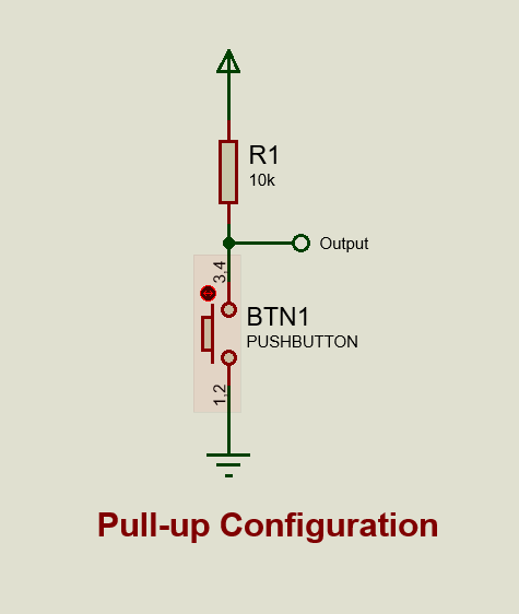
You can start by figuring out whether the pushbuttons work in a pull-up or a pull-down circuit. This can be done relatively easily by simply observing the circuit or by powering up the circuit and testing the voltage at the outputs of the pushbuttons when they are pressed and when they are released. From what I have seen, pushbuttons in most circuits work in a pull-up configuration.
Once that is done, you can move forward and trace the pads of the buttons on the Lutron Pico board to the vias they are connected to. Since you cannot solder to the pads from the front, you can solder wires to these vias from the back side of the board. You can then solder these wires to the pads of the pushbuttons on the LED controller board.
You'll also need to make sure that both of these circuits share a common ground.
Note: This will only work if pushbuttons on both of these circuits share the same configuration. Otherwise, the circuit will act like the buttons are pressed when they are not.

