mentioned the advantage of this circuit
Source Link
sai
  • 4.4k
  • 1
  • 3
  • 14

enter image description here

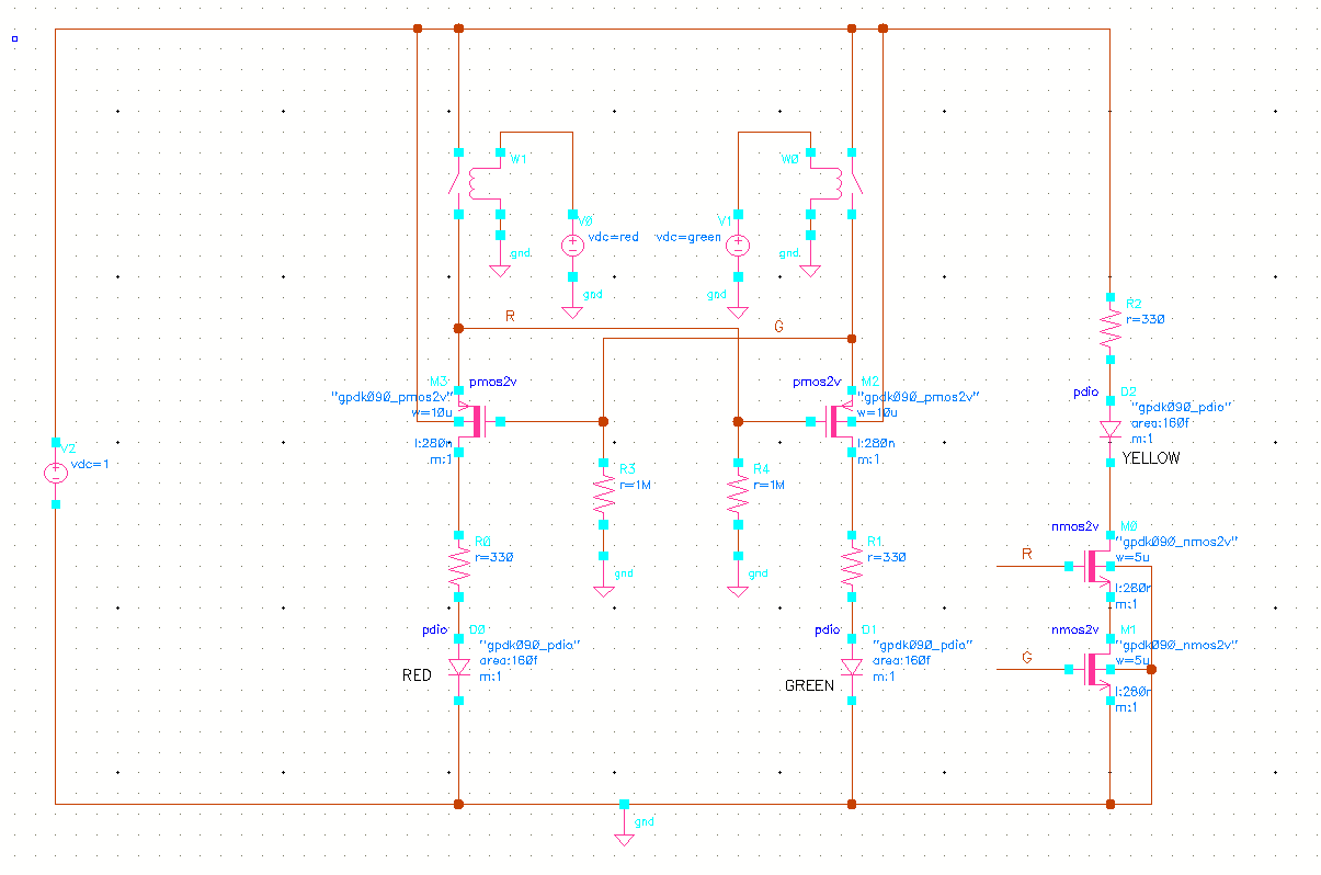
There are many solutions possible. Here is one implemented using MOSFETs. In your schematic, I assume D3 is yellow. If VCC is sufficiently high, it will be always ON irrespective of S1, S2 and there will be very high current through Q1 because there is no resistor to limit the current.

Edit: The high current through Q1 is if switch S1 is also ON.

One advantage of the scheme proposed here is that there is minimal wastage of current.

enter image description here

There are many solutions possible. Here is one implemented using MOSFETs. In your schematic, I assume D3 is yellow. If VCC is sufficiently high, it will be always ON irrespective of S1, S2 and there will be very high current through Q1 because there is no resistor to limit the current.

Edit: The high current through Q1 is if switch S1 is also ON.

One advantage of the scheme proposed here is that there is minimal wastage of current.
I updated the diagram to make it more readable
Source Link
sai
  • 4.4k
  • 1
  • 3
  • 14

enter image description hereenter image description here

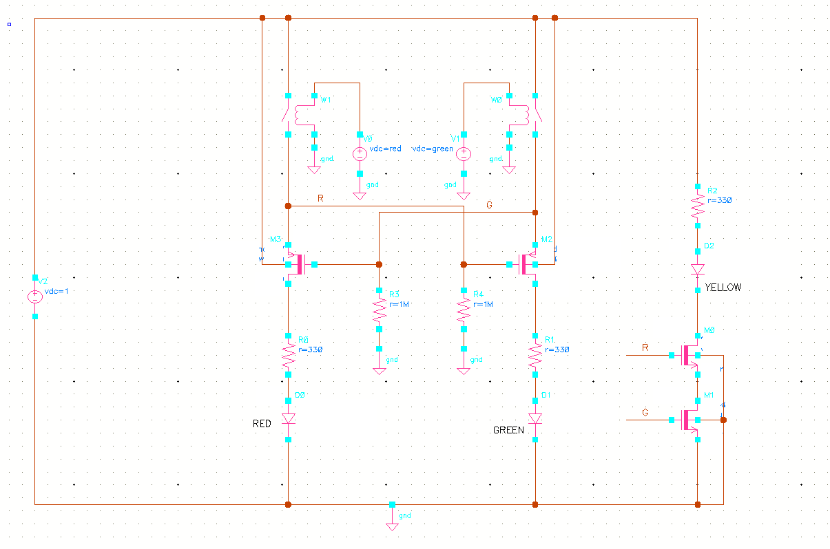
There are many solutions possible. Here is one implemented using MOSFETs. In your schematic, I assume D3 is yellow. If VCC is sufficiently high, it will be always ON irrespective of S1, S2 and there will be very high current through Q1 because there is no resistor to limit the current.

Edit: The high current through Q1 is if switch S1 is also ON.

enter image description here

There are many solutions possible. Here is one implemented using MOSFETs. In your schematic, I assume D3 is yellow. If VCC is sufficiently high, it will be always ON irrespective of S1, S2 and there will be very high current through Q1 because there is no resistor to limit the current.

Edit: The high current through Q1 is if switch S1 is also ON.

added 65 characters in body
Source Link
sai
  • 4.4k
  • 1
  • 3
  • 14

enter image description here

There are many solutions possible. Here is one implemented using MOSFETs. In your schematic, I assume D3 is yellow. If VCC is sufficiently high, it will be always ON irrespective of S1, S2 and there will be very high current through Q1 because there is no resistor to limit the current.

Edit: The high current through Q1 is if switch S1 is also ON.

enter image description here

There are many solutions possible. Here is one implemented using MOSFETs. In your schematic, I assume D3 is yellow. If VCC is sufficiently high, it will be always ON irrespective of S1, S2 and there will be very high current through Q1 because there is no resistor to limit the current.

Edit: The high current through Q1 is if switch S1 is also ON.

Source Link
sai
  • 4.4k
  • 1
  • 3
  • 14
Loading