added 1390 characters in body
Source Link
Olin Lathrop
  • 315.1k
  • 36
  • 441
  • 928

Here is a simple solution:
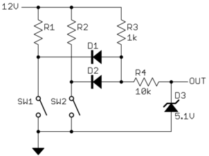
R1, R2, SW1, and SW2 represent the circuit in the car that you can't modify. D1 and D2 perform a OR function so that the bottom end of R3 goes low when either or both switches are closed. I would put D1, D2, and R3 close to where these switches are, then R4 by the PIC.

You have to assume the long line will pick up noise and transients, so R4 provides some impedance for D3 to work against to clamp the signal at the PIC to safe levels.

Added:

There is confusion as to whether or not you can get at the low sides of the loads. My first reaction was that this would be the easy way to connect because you only have to monitor the voltage. It therefore doesn't require breaking any connections, just tapping off existing connection points.

However, if it is really better to break into the high side power connection to the loads for some reason, then here is a simple way:
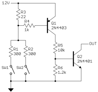
Again, R1, R2, SW1, and SW2 are the switches and loads that you presumably can't get into. This requires breaking the power connection to the loads and inserting R3, R4, and Q1. R3 is a current sense resistor sized to produce enough of a voltage drop to turn on Q1 when either of the loads is on. R4 is just to limit current thru the base of Q1 to safe levels.

The long wire to the PIC board is intended to be between the collector of Q1 and the top of R5. With the R5, R6, and Q2 receiving circuit, a lot of noise and nasty spikes can be tolerated on that line. When Q1 is on, Q2 will be driven on, which will drive OUT low. Th collector of Q2 goes directly to a PIC pin with a internal pullup. Noise shouldn't be much of a issue here since R5, R6, and Q2 are intended to be on the same board close to the PIC.

Overall, when a load is turned on, the PIC input will go low.

Here is a simple solution:

R1, R2, SW1, and SW2 represent the circuit in the car that you can't modify. D1 and D2 perform a OR function so that the bottom end of R3 goes low when either or both switches are closed. I would put D1, D2, and R3 close to where these switches are, then R4 by the PIC.

You have to assume the long line will pick up noise and transients, so R4 provides some impedance for D3 to work against to clamp the signal at the PIC to safe levels.

Added:

There is confusion as to whether or not you can get at the low sides of the loads. My first reaction was that this would be the easy way to connect because you only have to monitor the voltage. It therefore doesn't require breaking any connections, just tapping off existing connection points.

However, if it is really better to break into the high side power connection to the loads for some reason, then here is a simple way:

Again, R1, R2, SW1, and SW2 are the switches and loads that you presumably can't get into. This requires breaking the power connection to the loads and inserting R3, R4, and Q1. R3 is a current sense resistor sized to produce enough of a voltage drop to turn on Q1 when either of the loads is on. R4 is just to limit current thru the base of Q1 to safe levels.

The long wire to the PIC board is intended to be between the collector of Q1 and the top of R5. With the R5, R6, and Q2 receiving circuit, a lot of noise and nasty spikes can be tolerated on that line. When Q1 is on, Q2 will be driven on, which will drive OUT low. Th collector of Q2 goes directly to a PIC pin with a internal pullup. Noise shouldn't be much of a issue here since R5, R6, and Q2 are intended to be on the same board close to the PIC.

Overall, when a load is turned on, the PIC input will go low.

Source Link
Olin Lathrop
  • 315.1k
  • 36
  • 441
  • 928

Here is a simple solution:

R1, R2, SW1, and SW2 represent the circuit in the car that you can't modify. D1 and D2 perform a OR function so that the bottom end of R3 goes low when either or both switches are closed. I would put D1, D2, and R3 close to where these switches are, then R4 by the PIC.

You have to assume the long line will pick up noise and transients, so R4 provides some impedance for D3 to work against to clamp the signal at the PIC to safe levels.