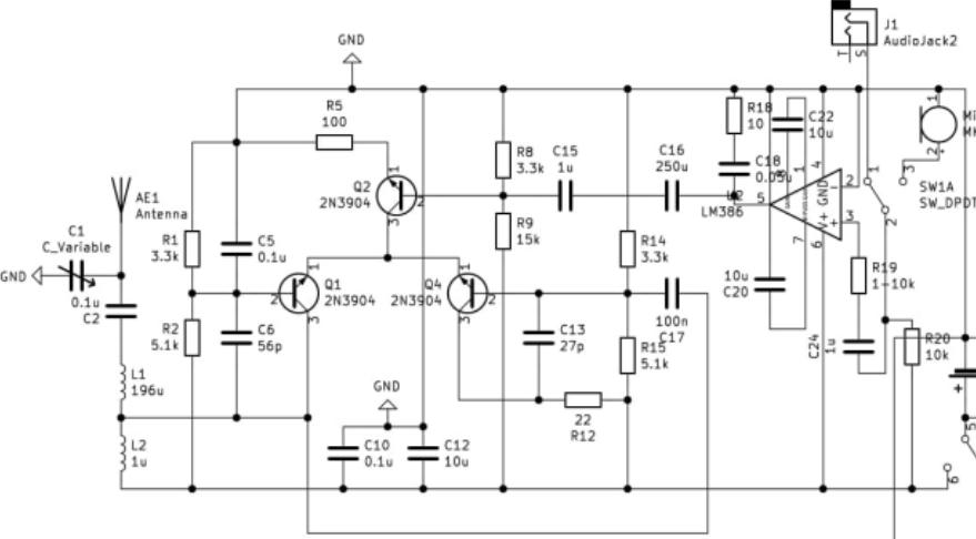
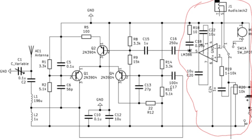
I have been trying to make an amAM transmitter and I found this schematic from a persons college project. I understand what is circled in red but the rest I am struggling with. The part circled in red is in audio input and amplification. I also know that this project uses a Hartley oscillator to generate the carrier wave (535-1705khz1705 kHz) and that it uses one transistor for the amplitude modulation process. But I am very confused on how these work together and where they are on the circuit. His full project is on the link: https://web.mit.edu/6.101/www/s2020/projects/omotunde_Project_Final_Report.pdf
I would really appreciate if someone could highlight where the oscillator is and explain in this circuit, how amplitude modulation actually happens.


