added 286 characters in body
Source Link
kam1212
  • 693
  • 1
  • 15

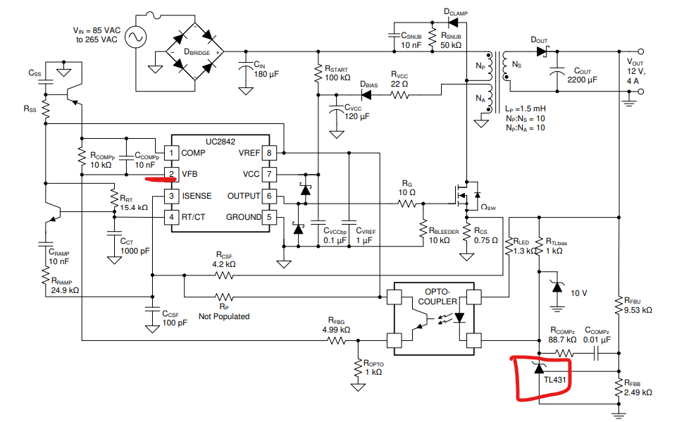
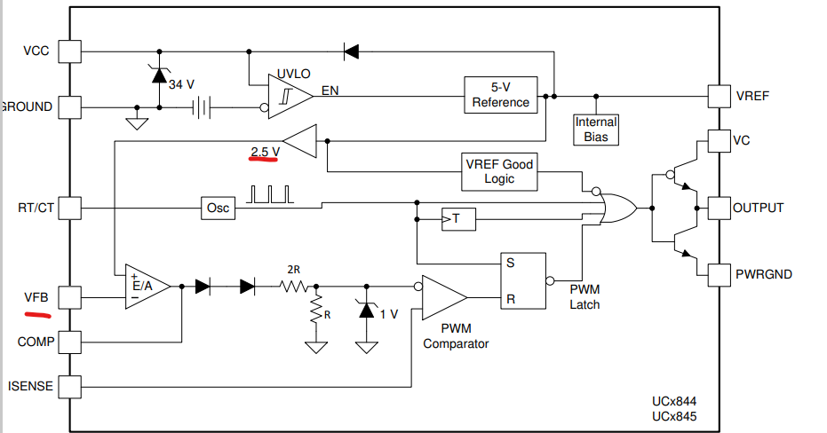
I have a slight confusion regarding the UCC3895UCC3895, which is a four-channel wave generator. Earlier I had worked on the UC3842UC3842 and therefore to see better results I wanted to take a look at the UCC3895. The UC3842 IC has an internal 2.5 V reference voltage set inside the IC so that if the voltage due to the divider on the TL431 changes, then accordingly due to the closed feedback loop it will adjust that voltage and bring it to 2.5 V in order to eliminate the error from the error amplifier:

enter image description here

enter image description here

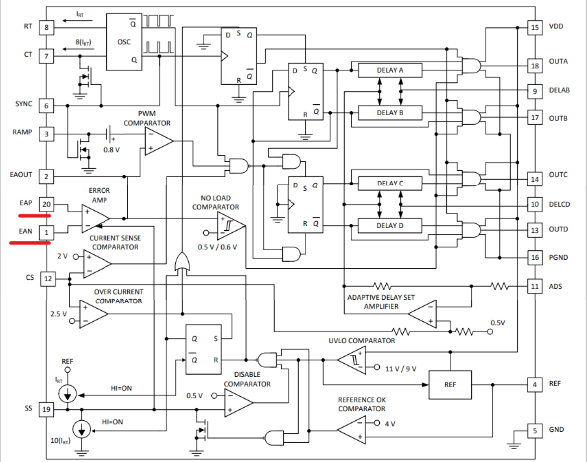
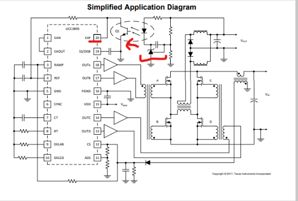
Now moving further towards the UCC3895. In the internal diagram of the UCC3895 I cant find out any internal reference as set here in UC3842 i.e. 2.5 V. There is the same TL431 whose feedback is moving to one end of the error amplifier. How is the IC being able to know its fixed reference? The TL431 just gives the feedback input as done in the UC3842 as well but there was a 2.5 V reference internally and here the reference is missing inside the IC. Previously I asked a similar question but wasn't able to get my confusion clear therefore I wanted to make the question clear.

Kindly help me how the IC is being able to figure out the fixed reference for the IC?

Below are the internal and external complete diagrams:

enter image description here

enter image description here

I have a slight confusion regarding the UCC3895, which is a four-channel wave generator. Earlier I had worked on the UC3842 and therefore to see better results I wanted to take a look at the UCC3895. The UC3842 IC has an internal 2.5 V reference voltage set inside the IC so that if the voltage due to the divider on the TL431 changes, then accordingly due to the closed feedback loop it will adjust that voltage and bring it to 2.5 V in order to eliminate the error from the error amplifier:

enter image description here

enter image description here

Now moving further towards the UCC3895. In the internal diagram of the UCC3895 I cant find out any internal reference as set here in UC3842 i.e. 2.5 V. There is the same TL431 whose feedback is moving to one end of the error amplifier. How is the IC being able to know its fixed reference? The TL431 just gives the feedback input as done in the UC3842 as well but there was a 2.5 V reference internally and here the reference is missing inside the IC. Previously I asked a similar question but wasn't able to get my confusion clear therefore I wanted to make the question clear.

Kindly help me how the IC is being able to figure out the fixed reference for the IC?

Below are the internal and external complete diagrams:
enter image description here

enter image description here

I have a slight confusion regarding the UCC3895, which is a four-channel wave generator. Earlier I had worked on the UC3842 and therefore to see better results I wanted to take a look at the UCC3895. The UC3842 IC has an internal 2.5 V reference voltage set inside the IC so that if the voltage due to the divider on the TL431 changes, then accordingly due to the closed feedback loop it will adjust that voltage and bring it to 2.5 V in order to eliminate the error from the error amplifier:

enter image description here

enter image description here

Now moving further towards the UCC3895. In the internal diagram of the UCC3895 I cant find out any internal reference as set here in UC3842 i.e. 2.5 V. There is the same TL431 whose feedback is moving to one end of the error amplifier. How is the IC being able to know its fixed reference? The TL431 just gives the feedback input as done in the UC3842 as well but there was a 2.5 V reference internally and here the reference is missing inside the IC. Previously I asked a similar question but wasn't able to get my confusion clear therefore I wanted to make the question clear.

Kindly help me how the IC is being able to figure out the fixed reference for the IC?

Below are the internal and external complete diagrams:
enter image description here

enter image description here

added 4 characters in body; edited title
Source Link
JYelton
  • 34.9k
  • 34
  • 147
  • 272

UCC3895- VS UC3842 based smps-based SMPS designs

I have a slight confusion regarding the UCC3895, which is a four channel-channel wave generator. Earlier I had worked on the UC3842 and therefore to see better results I wanted to take a look at the UCC3895. The UC3842 IC has an internal 2.5V5 V reference voltage set inside the IC so that if the voltage due to the divider on the TL431 changes,then then accordingly due to the closed feedback loop it will adjust that voltage and bring it to 2.5V inorder5 V in order to eliminate the error from the error amplifier:   

enter image description here

enter image description here

Now moving further towards the UCC3895. In the internal diagram of the UCC3895 I cant find out any internal reference as set here in UC3842 iei.e. 2.5V5 V. There is the same TL431 whose feedback is moving to one end of the error amplifier. How is the IC being able to know its fixed reference? The TL431 just gives the feedback input as done in the UC3842 as well but there was a 2.5V5 V reference internally and here the reference is missing inside the IC. Previously I asked a similar question but wasn't able to get my confusion clear therefore I wanted to make the question clear.
Kindly

Kindly help me how the IC is being able to figure out the fixed reference for the IC? Below

Below are the internal and external complete diagrams:

enter image description here

enter image description here

UCC3895 VS UC3842 based smps designs

I have a slight confusion regarding the UCC3895, which is a four channel wave generator. Earlier I had worked on the UC3842 and therefore to see better results I wanted to take a look at the UCC3895. The UC3842 IC has an internal 2.5V reference voltage set inside the IC so that if the voltage due to the divider on the TL431 changes,then accordingly due to the closed feedback loop it will adjust that voltage and bring it to 2.5V inorder to eliminate the error from the error amplifier:  enter image description here

enter image description here

Now moving further towards the UCC3895. In the internal diagram of the UCC3895 I cant find out any internal reference as set here in UC3842 ie 2.5V. There is the same TL431 whose feedback is moving to one end of the error amplifier. How is the IC being able to know its fixed reference? The TL431 just gives the feedback input as done in the UC3842 as well but there was a 2.5V reference internally and here the reference is missing inside the IC. Previously I asked a similar question but wasn't able to get my confusion clear therefore I wanted to make the question clear.
Kindly help me how the IC is being able to figure out the fixed reference for the IC? Below are the internal and external complete diagrams:
enter image description here

enter image description here

UCC3895- VS UC3842-based SMPS designs

I have a slight confusion regarding the UCC3895, which is a four-channel wave generator. Earlier I had worked on the UC3842 and therefore to see better results I wanted to take a look at the UCC3895. The UC3842 IC has an internal 2.5 V reference voltage set inside the IC so that if the voltage due to the divider on the TL431 changes, then accordingly due to the closed feedback loop it will adjust that voltage and bring it to 2.5 V in order to eliminate the error from the error amplifier: 

enter image description here

enter image description here

Now moving further towards the UCC3895. In the internal diagram of the UCC3895 I cant find out any internal reference as set here in UC3842 i.e. 2.5 V. There is the same TL431 whose feedback is moving to one end of the error amplifier. How is the IC being able to know its fixed reference? The TL431 just gives the feedback input as done in the UC3842 as well but there was a 2.5 V reference internally and here the reference is missing inside the IC. Previously I asked a similar question but wasn't able to get my confusion clear therefore I wanted to make the question clear.

Kindly help me how the IC is being able to figure out the fixed reference for the IC?

Below are the internal and external complete diagrams:
enter image description here

enter image description here

Source Link
kam1212
  • 693
  • 1
  • 15

UCC3895 VS UC3842 based smps designs

I have a slight confusion regarding the UCC3895, which is a four channel wave generator. Earlier I had worked on the UC3842 and therefore to see better results I wanted to take a look at the UCC3895. The UC3842 IC has an internal 2.5V reference voltage set inside the IC so that if the voltage due to the divider on the TL431 changes,then accordingly due to the closed feedback loop it will adjust that voltage and bring it to 2.5V inorder to eliminate the error from the error amplifier: enter image description here

enter image description here

Now moving further towards the UCC3895. In the internal diagram of the UCC3895 I cant find out any internal reference as set here in UC3842 ie 2.5V. There is the same TL431 whose feedback is moving to one end of the error amplifier. How is the IC being able to know its fixed reference? The TL431 just gives the feedback input as done in the UC3842 as well but there was a 2.5V reference internally and here the reference is missing inside the IC. Previously I asked a similar question but wasn't able to get my confusion clear therefore I wanted to make the question clear.
Kindly help me how the IC is being able to figure out the fixed reference for the IC? Below are the internal and external complete diagrams:

enter image description here

enter image description here