added 5 characters in body
Source Link
Math Keeps Me Busy
  • 27.8k
  • 5
  • 25
  • 87

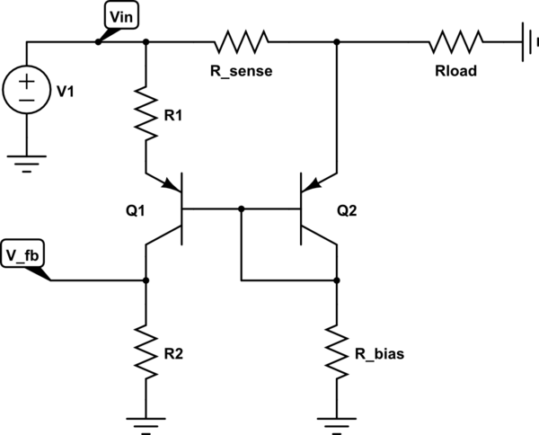
As mentioned elsewhere, there are many ways to approximate a circuit, and each gives some insight into how a circuit works. Here is how I would analyze this circuit to gain insight into its approximate workings.
schematic

simulate this circuit – Schematic created using CircuitLab

I would first note that bases of Q1 and Q2 are tied together. That means the base voltages are the same.

If the \$V_{BE}\$ of each transistor is the same, then the voltages at the emitters referenced to ground will also be the same.

If the transistors are similar, and have similar current, similar temperature, etc, then it is a good approximation that the \$V_{BE}\$'s will be the same.

If the \$V_{BE}\$ of each transistor is the same, then the voltages at the emitters referenced to ground will also be the same.

$$V_{E(Q1)} \approx V_{E(Q2)}$$

From this it follows that the voltage drops across \$R_1\$ and \$R_{sense}\$ must be approximately the same.

$$I_{sense}R_{sense} \approx I_{R1}R1$$

or, rearranged

$$I_{R1} = I_{sense}\frac{R_{sense}}{R1}$$$$I_{R1} \approx I_{sense}\frac{R_{sense}}{R1}$$

If the base current of Q1 and the feedback current are small in comparison to \$I_{R1}\$

then

$$I_{R1} \approx I_{R2}$$

But

$$V_{fb} = I_{R2}R2$$

So,

$$V_{fb} \approx I_{sense}\frac{R_{sense}}{R1}R2 = \frac{I_{sense}R_{sense}R2}{R1}$$

If we make one more approximation,

$$I_{load} \approx I_{sense}$$

we get an approximate relationship between \$I_{sense}\$\$I_{load}\$ and \$V_{fb}\$.

$$V_{fb} \approx \frac{I_{load}R_{sense}R2}{R1}$$

Obviously there have been multiple approximations made, but I think this approach gives rather direct insight into how \$V_{fb}\$ is related to \$I_{sense}\$\$I_{load}\$.

As mentioned elsewhere, there are many ways to approximate a circuit, and each gives some insight into how a circuit works. Here is how I would analyze this circuit to gain insight into its approximate workings.

schematic

simulate this circuit – Schematic created using CircuitLab

I would first note that bases of Q1 and Q2 are tied together. That means the base voltages are the same.

If the \$V_{BE}\$ of each transistor is the same, then the voltages at the emitters referenced to ground will also be the same.

If the transistors are similar, and have similar current, similar temperature, etc, then it is a good approximation that the \$V_{BE}\$'s will be the same.

$$V_{E(Q1)} \approx V_{E(Q2)}$$

From this it follows that the voltage drops across \$R_1\$ and \$R_{sense}\$ must be approximately the same.

$$I_{sense}R_{sense} \approx I_{R1}R1$$

or, rearranged

$$I_{R1} = I_{sense}\frac{R_{sense}}{R1}$$

If the base current of Q1 and the feedback current are small in comparison to \$I_{R1}\$

then

$$I_{R1} \approx I_{R2}$$

But

$$V_{fb} = I_{R2}R2$$

So,

$$V_{fb} \approx I_{sense}\frac{R_{sense}}{R1}R2 = \frac{I_{sense}R_{sense}R2}{R1}$$

If we make one more approximation,

$$I_{load} \approx I_{sense}$$

we get an approximate relationship between \$I_{sense}\$ and \$V_{fb}\$.

$$V_{fb} \approx \frac{I_{load}R_{sense}R2}{R1}$$

Obviously there have been multiple approximations made, but I think this approach gives rather direct insight into how \$V_{fb}\$ is related to \$I_{sense}\$.

As mentioned elsewhere, there are many ways to approximate a circuit, and each gives some insight into how a circuit works. Here is how I would analyze this circuit to gain insight into its approximate workings.

schematic

simulate this circuit – Schematic created using CircuitLab

I would first note that bases of Q1 and Q2 are tied together. That means the base voltages are the same.

If the transistors are similar, and have similar current, similar temperature, etc, then it is a good approximation that the \$V_{BE}\$'s will be the same.

If the \$V_{BE}\$ of each transistor is the same, then the voltages at the emitters referenced to ground will also be the same.

$$V_{E(Q1)} \approx V_{E(Q2)}$$

From this it follows that the voltage drops across \$R_1\$ and \$R_{sense}\$ must be approximately the same.

$$I_{sense}R_{sense} \approx I_{R1}R1$$

or, rearranged

$$I_{R1} \approx I_{sense}\frac{R_{sense}}{R1}$$

If the base current of Q1 and the feedback current are small in comparison to \$I_{R1}\$

then

$$I_{R1} \approx I_{R2}$$

But

$$V_{fb} = I_{R2}R2$$

So,

$$V_{fb} \approx I_{sense}\frac{R_{sense}}{R1}R2 = \frac{I_{sense}R_{sense}R2}{R1}$$

If we make one more approximation,

$$I_{load} \approx I_{sense}$$

we get an approximate relationship between \$I_{load}\$ and \$V_{fb}\$.

$$V_{fb} \approx \frac{I_{load}R_{sense}R2}{R1}$$

Obviously there have been multiple approximations made, but I think this approach gives rather direct insight into how \$V_{fb}\$ is related to \$I_{load}\$.

deleted 2 characters in body
Source Link
Math Keeps Me Busy
  • 27.8k
  • 5
  • 25
  • 87

As mentioned elsewhere, there are many ways to approximate a circuit, and each gives some insight into how a circuit works. Here is how I would analyze this circuit to gain insight into its approximate workings.

schematic

simulate this circuit – Schematic created using CircuitLab

I would first note that bases of Q1 and Q2 are tied together. That means the base voltages are the same.

If the \$V_{BE}\$ of each transistor is the same, then the voltages at the emitters referenced to ground will also be the same.

If the transistors are similar, and have similar current, similar temperature, etc, then it is a good approximation that the \$V_{BE}\$'s will be the same.

$$V_{E(Q1)} \approx V_{E(Q2)}$$

From this it follows that the voltage drops across \$R_1\$ and \$R_{sense}\$ must be approximately the same.

$$I_{sense}R_{sense} \approx I_{R1}R1$$

or, rearranged

$$I_{R1} = I_{sense}\frac{R_{sense}}{R1}$$

If the base current of Q1 and the feedback current are small in comparison to \$I_{R1}\$

then

$$I_{R1} \approx I_{R2}$$

But

$$V_{fb} = I_{R2}R2$$

So,

$$V_{fb} \approx I_{sense}\frac{R_{sense}}{R1}R2 = \frac{I_{sense}R_{sense}R2}{R1}$$

If we make one more approximation,

$$I_{load} \approx \$I_{sense}$$$$I_{load} \approx I_{sense}$$

we get an approximate relationship between \$I_{sense}\$ and \$V_{fb}\$.

$$V_{fb} \approx \frac{I_{load}R_{sense}R2}{R1}$$

Obviously there have been multiple approximations made, but I think this approach gives rather direct insight into how \$V_{fb}\$ is related to \$I_{sense}\$.

As mentioned elsewhere, there are many ways to approximate a circuit, and each gives some insight into how a circuit works. Here is how I would analyze this circuit to gain insight into its approximate workings.

schematic

simulate this circuit – Schematic created using CircuitLab

I would first note that bases of Q1 and Q2 are tied together. That means the base voltages are the same.

If the \$V_{BE}\$ of each transistor is the same, then the voltages at the emitters referenced to ground will also be the same.

If the transistors are similar, and have similar current, similar temperature, etc, then it is a good approximation that the \$V_{BE}\$'s will be the same.

$$V_{E(Q1)} \approx V_{E(Q2)}$$

From this it follows that the voltage drops across \$R_1\$ and \$R_{sense}\$ must be approximately the same.

$$I_{sense}R_{sense} \approx I_{R1}R1$$

or, rearranged

$$I_{R1} = I_{sense}\frac{R_{sense}}{R1}$$

If the base current of Q1 and the feedback current are small in comparison to \$I_{R1}\$

then

$$I_{R1} \approx I_{R2}$$

But

$$V_{fb} = I_{R2}R2$$

So,

$$V_{fb} \approx I_{sense}\frac{R_{sense}}{R1}R2 = \frac{I_{sense}R_{sense}R2}{R1}$$

If we make one more approximation,

$$I_{load} \approx \$I_{sense}$$

we get an approximate relationship between \$I_{sense}\$ and \$V_{fb}\$.

$$V_{fb} \approx \frac{I_{load}R_{sense}R2}{R1}$$

Obviously there have been multiple approximations made, but I think this approach gives rather direct insight into how \$V_{fb}\$ is related to \$I_{sense}\$.

As mentioned elsewhere, there are many ways to approximate a circuit, and each gives some insight into how a circuit works. Here is how I would analyze this circuit to gain insight into its approximate workings.

schematic

simulate this circuit – Schematic created using CircuitLab

I would first note that bases of Q1 and Q2 are tied together. That means the base voltages are the same.

If the \$V_{BE}\$ of each transistor is the same, then the voltages at the emitters referenced to ground will also be the same.

If the transistors are similar, and have similar current, similar temperature, etc, then it is a good approximation that the \$V_{BE}\$'s will be the same.

$$V_{E(Q1)} \approx V_{E(Q2)}$$

From this it follows that the voltage drops across \$R_1\$ and \$R_{sense}\$ must be approximately the same.

$$I_{sense}R_{sense} \approx I_{R1}R1$$

or, rearranged

$$I_{R1} = I_{sense}\frac{R_{sense}}{R1}$$

If the base current of Q1 and the feedback current are small in comparison to \$I_{R1}\$

then

$$I_{R1} \approx I_{R2}$$

But

$$V_{fb} = I_{R2}R2$$

So,

$$V_{fb} \approx I_{sense}\frac{R_{sense}}{R1}R2 = \frac{I_{sense}R_{sense}R2}{R1}$$

If we make one more approximation,

$$I_{load} \approx I_{sense}$$

we get an approximate relationship between \$I_{sense}\$ and \$V_{fb}\$.

$$V_{fb} \approx \frac{I_{load}R_{sense}R2}{R1}$$

Obviously there have been multiple approximations made, but I think this approach gives rather direct insight into how \$V_{fb}\$ is related to \$I_{sense}\$.

Source Link
Math Keeps Me Busy
  • 27.8k
  • 5
  • 25
  • 87

As mentioned elsewhere, there are many ways to approximate a circuit, and each gives some insight into how a circuit works. Here is how I would analyze this circuit to gain insight into its approximate workings.

schematic

simulate this circuit – Schematic created using CircuitLab

I would first note that bases of Q1 and Q2 are tied together. That means the base voltages are the same.

If the \$V_{BE}\$ of each transistor is the same, then the voltages at the emitters referenced to ground will also be the same.

If the transistors are similar, and have similar current, similar temperature, etc, then it is a good approximation that the \$V_{BE}\$'s will be the same.

$$V_{E(Q1)} \approx V_{E(Q2)}$$

From this it follows that the voltage drops across \$R_1\$ and \$R_{sense}\$ must be approximately the same.

$$I_{sense}R_{sense} \approx I_{R1}R1$$

or, rearranged

$$I_{R1} = I_{sense}\frac{R_{sense}}{R1}$$

If the base current of Q1 and the feedback current are small in comparison to \$I_{R1}\$

then

$$I_{R1} \approx I_{R2}$$

But

$$V_{fb} = I_{R2}R2$$

So,

$$V_{fb} \approx I_{sense}\frac{R_{sense}}{R1}R2 = \frac{I_{sense}R_{sense}R2}{R1}$$

If we make one more approximation,

$$I_{load} \approx \$I_{sense}$$

we get an approximate relationship between \$I_{sense}\$ and \$V_{fb}\$.

$$V_{fb} \approx \frac{I_{load}R_{sense}R2}{R1}$$

Obviously there have been multiple approximations made, but I think this approach gives rather direct insight into how \$V_{fb}\$ is related to \$I_{sense}\$.