Rollback to Revision 4 - this rollback has been done to stop the question becoming a "chameleon question" as it has already received answers, so expanding it is no longer allowed. (comment edited Nov 6, 2023 at 13:52)
Source Link
SamGibson
  • 18.3k
  • 5
  • 41
  • 63

ZMPT101B

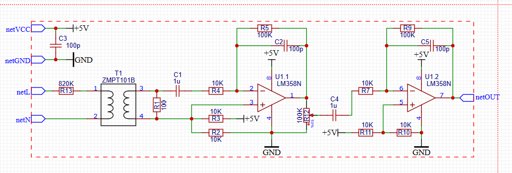
I am interested in the ZMPT101B circuit and there are a few things I cannot understand.

This circuit is designed to measure AC Main voltages between 50Hz and 80-250V and to be read from an MCU like Arduino. (This is the module that sells a lot on the web.)

  1. ✅ (Answered) Why did we superimpose the signal from opamp 1 (U1.1) on 2.5V and then eliminate the DC component with capacitor C4? Couldn't we not overlap 2.5V? Was this really necessary?

  2. ❌ (Waiting) What is the purpose of capacitors C2 and C5 considering the measurement purpose, measurement voltage and frequency? What could they be used for in this circuit? Could it be something like an integrator? (Input: 50 Hz / 80-220V, Output: 0-3.5V ac main line voltage meter)

  3. ✅ (Answered) The ZMPT101B is a current transformer. So we can bring the voltage to the value we want with the R1 resistor. Then why did we try to get 10 to 100 times gain with 2 opamps. Couldn't we increase the R1 resistor and make 10 times gain with a single opamp? Or could we not make 100 times without changing the R1 resistor? Was 2 opamp circuits used just to avoid inverting?

  4. ✅ (Answered) I cannot get 5V output in the simulation. 1.5V clipping. Therefore, I can get a maximum output of 3.5V. If I make pin 8 of the last opamp 6.5V instead of 5V, the output can go up to 5V. What is the reason for this?

  5. ✅ (Answered) With resistor R12 we can reduce the output of the first opamp. This circuit is normally designed for voltages up to 250V, but theoretically even 1000V seems to be measurable. I can see this in the simulation. Will this cause a problem in practice?

  6. ✅ (Answered) Wouldn't it be much simpler if instead of this opamp circuit, we set the R1 resistor according to the range we want (maybe using a potentiometer) and use a zener diode so that the output does not exceed 5V? What would be the disadvantage?

  7. ❌ (Waiting) Why is the lower leg of R1 connected to the middle of R2 and R3? What is the purpose here?

  8. ❌ (Waiting) Is this a voltage transformer or a current transformer? What is the difference and how can you tell by looking at this circuit? (I will open a more detailed question about this)

  9. ❌ (Waiting) When determining the R1 value, which data in the datasheet is used for the heating state of the transformer and with which formulas is it calculated?

I did the simulation but I could not find the answer to my questions.
ZMPT101B

I am interested in the ZMPT101B circuit and there are a few things I cannot understand.

This circuit is designed to measure AC Main voltages between 50Hz and 80-250V and to be read from an MCU like Arduino. (This is the module that sells a lot on the web.)

  1. Why did we superimpose the signal from opamp 1 (U1.1) on 2.5V and then eliminate the DC component with capacitor C4? Couldn't we not overlap 2.5V? Was this really necessary?

  2. What is the purpose of capacitors C2 and C5? What could they be used for in this circuit?

  3. The ZMPT101B is a current transformer. So we can bring the voltage to the value we want with the R1 resistor. Then why did we try to get 10 to 100 times gain with 2 opamps. Couldn't we increase the R1 resistor and make 10 times gain with a single opamp? Or could we not make 100 times without changing the R1 resistor? Was 2 opamp circuits used just to avoid inverting?

  4. I cannot get 5V output in the simulation. 1.5V clipping. Therefore, I can get a maximum output of 3.5V. If I make pin 8 of the last opamp 6.5V instead of 5V, the output can go up to 5V. What is the reason for this?

  5. With resistor R12 we can reduce the output of the first opamp. This circuit is normally designed for voltages up to 250V, but theoretically even 1000V seems to be measurable. I can see this in the simulation. Will this cause a problem in practice?

  6. Wouldn't it be much simpler if instead of this opamp circuit, we set the R1 resistor according to the range we want (maybe using a potentiometer) and use a zener diode so that the output does not exceed 5V? What would be the disadvantage?

I did the simulation but I could not find the answer to my questions.

added 634 characters in body
Source Link

ZMPT101B

I am interested in the ZMPT101B circuit and there are a few things I cannot understand.

This circuit is designed to measure AC Main voltages between 50Hz and 80-250V and to be read from an MCU like Arduino. (This is the module that sells a lot on the web.)

  1. ✅ (Answered) Why did we superimpose the signal from opamp 1 (U1.1) on 2.5V and then eliminate the DC component with capacitor C4? Couldn't we not overlap 2.5V? Was this really necessary?

  2. ❌ (Waiting) What is the purpose of capacitors C2 and C5 considering the measurement purpose, measurement voltage and frequency? What could they be used for in this circuit? Could it be something like an integrator? (Input: 50 Hz / 80-220V, Output: 0-3.5V ac main line voltage meter)

  3. ✅ (Answered) The ZMPT101B is a current transformer. So we can bring the voltage to the value we want with the R1 resistor. Then why did we try to get 10 to 100 times gain with 2 opamps. Couldn't we increase the R1 resistor and make 10 times gain with a single opamp? Or could we not make 100 times without changing the R1 resistor? Was 2 opamp circuits used just to avoid inverting?

  4. ✅ (Answered) I cannot get 5V output in the simulation. 1.5V clipping. Therefore, I can get a maximum output of 3.5V. If I make pin 8 of the last opamp 6.5V instead of 5V, the output can go up to 5V. What is the reason for this?

  5. ✅ (Answered) With resistor R12 we can reduce the output of the first opamp. This circuit is normally designed for voltages up to 250V, but theoretically even 1000V seems to be measurable. I can see this in the simulation. Will this cause a problem in practice?

  6. ✅ (Answered) Wouldn't it be much simpler if instead of this opamp circuit, we set the R1 resistor according to the range we want (maybe using a potentiometer) and use a zener diode so that the output does not exceed 5V? What would be the disadvantage?

  7. ❌ (Waiting) Why is the lower leg of R1 connected to the middle of R2 and R3? What is the purpose here?

  8. ❌ (Waiting) Is this a voltage transformer or a current transformer? What is the difference and how can you tell by looking at this circuit? (I will open a more detailed question about this)

  9. ❌ (Waiting) When determining the R1 value, which data in the datasheet is used for the heating state of the transformer and with which formulas is it calculated?

I did the simulation but I could not find the answer to my questions.

ZMPT101B

I am interested in the ZMPT101B circuit and there are a few things I cannot understand.

This circuit is designed to measure AC Main voltages between 50Hz and 80-250V and to be read from an MCU like Arduino. (This is the module that sells a lot on the web.)

  1. Why did we superimpose the signal from opamp 1 (U1.1) on 2.5V and then eliminate the DC component with capacitor C4? Couldn't we not overlap 2.5V? Was this really necessary?

  2. What is the purpose of capacitors C2 and C5? What could they be used for in this circuit?

  3. The ZMPT101B is a current transformer. So we can bring the voltage to the value we want with the R1 resistor. Then why did we try to get 10 to 100 times gain with 2 opamps. Couldn't we increase the R1 resistor and make 10 times gain with a single opamp? Or could we not make 100 times without changing the R1 resistor? Was 2 opamp circuits used just to avoid inverting?

  4. I cannot get 5V output in the simulation. 1.5V clipping. Therefore, I can get a maximum output of 3.5V. If I make pin 8 of the last opamp 6.5V instead of 5V, the output can go up to 5V. What is the reason for this?

  5. With resistor R12 we can reduce the output of the first opamp. This circuit is normally designed for voltages up to 250V, but theoretically even 1000V seems to be measurable. I can see this in the simulation. Will this cause a problem in practice?

  6. Wouldn't it be much simpler if instead of this opamp circuit, we set the R1 resistor according to the range we want (maybe using a potentiometer) and use a zener diode so that the output does not exceed 5V? What would be the disadvantage?

  7. Why is the lower leg of R1 connected to the middle of R2 and R3? What is the purpose here?

I did the simulation but I could not find the answer to my questions.

ZMPT101B

I am interested in the ZMPT101B circuit and there are a few things I cannot understand.

This circuit is designed to measure AC Main voltages between 50Hz and 80-250V and to be read from an MCU like Arduino. (This is the module that sells a lot on the web.)

  1. ✅ (Answered) Why did we superimpose the signal from opamp 1 (U1.1) on 2.5V and then eliminate the DC component with capacitor C4? Couldn't we not overlap 2.5V? Was this really necessary?

  2. ❌ (Waiting) What is the purpose of capacitors C2 and C5 considering the measurement purpose, measurement voltage and frequency? What could they be used for in this circuit? Could it be something like an integrator? (Input: 50 Hz / 80-220V, Output: 0-3.5V ac main line voltage meter)

  3. ✅ (Answered) The ZMPT101B is a current transformer. So we can bring the voltage to the value we want with the R1 resistor. Then why did we try to get 10 to 100 times gain with 2 opamps. Couldn't we increase the R1 resistor and make 10 times gain with a single opamp? Or could we not make 100 times without changing the R1 resistor? Was 2 opamp circuits used just to avoid inverting?

  4. ✅ (Answered) I cannot get 5V output in the simulation. 1.5V clipping. Therefore, I can get a maximum output of 3.5V. If I make pin 8 of the last opamp 6.5V instead of 5V, the output can go up to 5V. What is the reason for this?

  5. ✅ (Answered) With resistor R12 we can reduce the output of the first opamp. This circuit is normally designed for voltages up to 250V, but theoretically even 1000V seems to be measurable. I can see this in the simulation. Will this cause a problem in practice?

  6. ✅ (Answered) Wouldn't it be much simpler if instead of this opamp circuit, we set the R1 resistor according to the range we want (maybe using a potentiometer) and use a zener diode so that the output does not exceed 5V? What would be the disadvantage?

  7. ❌ (Waiting) Why is the lower leg of R1 connected to the middle of R2 and R3? What is the purpose here?

  8. ❌ (Waiting) Is this a voltage transformer or a current transformer? What is the difference and how can you tell by looking at this circuit? (I will open a more detailed question about this)

  9. ❌ (Waiting) When determining the R1 value, which data in the datasheet is used for the heating state of the transformer and with which formulas is it calculated?

I did the simulation but I could not find the answer to my questions.

Added a new question about the connection of R1 (question 7)
Source Link

ZMPT101B

I am interested in the ZMPT101B circuit and there are a few things I cannot understand.

This circuit is designed to measure AC Main voltages between 50Hz and 80-250V and to be read from an MCU like Arduino. (This is the module that sells a lot on the web.)

  1. Why did we superimpose the signal from opamp 1 (U1.1) on 2.5V and then eliminate the DC component with capacitor C4? Couldn't we not overlap 2.5V? Was this really necessary?

  2. What is the purpose of capacitors C2 and C5? What could they be used for in this circuit?

  3. The ZMPT101B is a current transformer. So we can bring the voltage to the value we want with the R1 resistor. Then why did we try to get 10 to 100 times gain with 2 opamps. Couldn't we increase the R1 resistor and make 10 times gain with a single opamp? Or could we not make 100 times without changing the R1 resistor? Was 2 opamp circuits used just to avoid inverting?

  4. I cannot get 5V output in the simulation. 1.5V clipping. Therefore, I can get a maximum output of 3.5V. If I make pin 8 of the last opamp 6.5V instead of 5V, the output can go up to 5V. What is the reason for this?

  5. With resistor R12 we can reduce the output of the first opamp. This circuit is normally designed for voltages up to 250V, but theoretically even 1000V seems to be measurable. I can see this in the simulation. Will this cause a problem in practice?

  6. Wouldn't it be much simpler if instead of this opamp circuit, we set the R1 resistor according to the range we want (maybe using a potentiometer) and use a zener diode so that the output does not exceed 5V? What would be the disadvantage?

  7. Why is the lower leg of R1 connected to the middle of R2 and R3? What is the purpose here?

I did the simulation but I could not find the answer to my questions.

ZMPT101B

I am interested in the ZMPT101B circuit and there are a few things I cannot understand.

This circuit is designed to measure AC Main voltages between 50Hz and 80-250V and to be read from an MCU like Arduino. (This is the module that sells a lot on the web.)

  1. Why did we superimpose the signal from opamp 1 (U1.1) on 2.5V and then eliminate the DC component with capacitor C4? Couldn't we not overlap 2.5V? Was this really necessary?

  2. What is the purpose of capacitors C2 and C5? What could they be used for in this circuit?

  3. The ZMPT101B is a current transformer. So we can bring the voltage to the value we want with the R1 resistor. Then why did we try to get 10 to 100 times gain with 2 opamps. Couldn't we increase the R1 resistor and make 10 times gain with a single opamp? Or could we not make 100 times without changing the R1 resistor? Was 2 opamp circuits used just to avoid inverting?

  4. I cannot get 5V output in the simulation. 1.5V clipping. Therefore, I can get a maximum output of 3.5V. If I make pin 8 of the last opamp 6.5V instead of 5V, the output can go up to 5V. What is the reason for this?

  5. With resistor R12 we can reduce the output of the first opamp. This circuit is normally designed for voltages up to 250V, but theoretically even 1000V seems to be measurable. I can see this in the simulation. Will this cause a problem in practice?

  6. Wouldn't it be much simpler if instead of this opamp circuit, we set the R1 resistor according to the range we want (maybe using a potentiometer) and use a zener diode so that the output does not exceed 5V? What would be the disadvantage?

  7. Why is the lower leg of R1 connected to the middle of R2 and R3? What is the purpose here?

I did the simulation but I could not find the answer to my questions.

added 50 characters in body
Source Link
Loading
added 122 characters in body
Source Link
Loading
added 103 characters in body
Source Link
Antonio51
  • 15.7k
  • 1
  • 9
  • 25
Loading
Source Link
Loading