Became Hot Network Question
Li-ion, not lithium (not rechargeable)
Source Link
Davide Andrea
  • 25.5k
  • 7
  • 38
  • 85

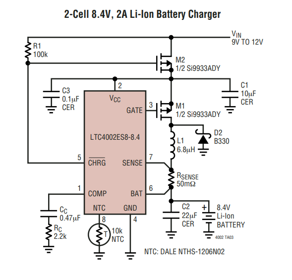
What is the function of the second MOSFET in this lithium-ion battery charger circuit?

I apologize if this an obvious question. This is my first time adding lithium-ion battery components to a circuit and I'm trying really hard to do all my homework and understand the function of everything to avoid accidental explosions.

I'm adding this battery charger IC to a circuit. I proceeded through the datasheet and did all my calculations / considerations expecting that at some point it would mention the purpose of the second P-MOSFET in the 8.4V diagram (see below,) but it never does.

enter image description here

In the single cell example a simple Schottky diode is used to isolate the input, and I'm assuming that is what the MOSFET is doing here as well. I've tried to break it down so I can understand its function.

Here is how I understand the circuit to work:

According to the datasheet, the charge pin is driven low when the device is in charging mode. When it's outside of charging mode (either because the input was disconnected or the device finished charging) the pin goes to high impedance, causing the pin to float. Charging mode starts when Vcc is greater than programmed battery voltage and stops after 3 hours.

So Vin gets plugged in, the body diode of M2 provides a path for Vcc to be driven to Vin, causing charge mode to start and CHRG to drive low which triggers M2 (which isn't necessary because we already have voltage passthrough because of the body diode.)

Then charging ends, CHRG goes to high impedance, causing the M2 Vgs to be positive closing M2 (accomplishing nothing because again we have the body diode of M2 passing voltage from Vin to Vcc.) If Vin is unplugged/drops to 0V before charging is done, then the IC goes into shutdown, which causes the same to occur.

Am I missing something here? It feels like there is no added benefit to doing the circuit like this. In other examples I've seen online other people appear to just use diodes, so why is the datasheet like this?

What is the function of the second MOSFET in this lithium battery charger circuit?

I apologize if this an obvious question. This is my first time adding lithium battery components to a circuit and I'm trying really hard to do all my homework and understand the function of everything to avoid accidental explosions.

I'm adding this battery charger IC to a circuit. I proceeded through the datasheet and did all my calculations / considerations expecting that at some point it would mention the purpose of the second P-MOSFET in the 8.4V diagram (see below,) but it never does.

enter image description here

In the single cell example a simple Schottky diode is used to isolate the input, and I'm assuming that is what the MOSFET is doing here as well. I've tried to break it down so I can understand its function.

Here is how I understand the circuit to work:

According to the datasheet, the charge pin is driven low when the device is in charging mode. When it's outside of charging mode (either because the input was disconnected or the device finished charging) the pin goes to high impedance, causing the pin to float. Charging mode starts when Vcc is greater than programmed battery voltage and stops after 3 hours.

So Vin gets plugged in, the body diode of M2 provides a path for Vcc to be driven to Vin, causing charge mode to start and CHRG to drive low which triggers M2 (which isn't necessary because we already have voltage passthrough because of the body diode.)

Then charging ends, CHRG goes to high impedance, causing the M2 Vgs to be positive closing M2 (accomplishing nothing because again we have the body diode of M2 passing voltage from Vin to Vcc.) If Vin is unplugged/drops to 0V before charging is done, then the IC goes into shutdown, which causes the same to occur.

Am I missing something here? It feels like there is no added benefit to doing the circuit like this. In other examples I've seen online other people appear to just use diodes, so why is the datasheet like this?

What is the function of the second MOSFET in this lithium-ion battery charger circuit?

I apologize if this an obvious question. This is my first time adding lithium-ion battery components to a circuit and I'm trying really hard to do all my homework and understand the function of everything to avoid accidental explosions.

I'm adding this battery charger IC to a circuit. I proceeded through the datasheet and did all my calculations / considerations expecting that at some point it would mention the purpose of the second P-MOSFET in the 8.4V diagram (see below,) but it never does.

enter image description here

In the single cell example a simple Schottky diode is used to isolate the input, and I'm assuming that is what the MOSFET is doing here as well. I've tried to break it down so I can understand its function.

Here is how I understand the circuit to work:

According to the datasheet, the charge pin is driven low when the device is in charging mode. When it's outside of charging mode (either because the input was disconnected or the device finished charging) the pin goes to high impedance, causing the pin to float. Charging mode starts when Vcc is greater than programmed battery voltage and stops after 3 hours.

So Vin gets plugged in, the body diode of M2 provides a path for Vcc to be driven to Vin, causing charge mode to start and CHRG to drive low which triggers M2 (which isn't necessary because we already have voltage passthrough because of the body diode.)

Then charging ends, CHRG goes to high impedance, causing the M2 Vgs to be positive closing M2 (accomplishing nothing because again we have the body diode of M2 passing voltage from Vin to Vcc.) If Vin is unplugged/drops to 0V before charging is done, then the IC goes into shutdown, which causes the same to occur.

Am I missing something here? It feels like there is no added benefit to doing the circuit like this. In other examples I've seen online other people appear to just use diodes, so why is the datasheet like this?

deleted 3 characters in body; edited title
Source Link
JRE
  • 73.5k
  • 10
  • 112
  • 194

Lithium Battery Charger circuit - Function What is the function of the second MOSFET in this lithium battery charger circuit?

I apologize if this an obvious question. This is my first time adding lithium battery components to a circuit and I'm trying really hard to do all my homework and understand the function of everything to avoid accidental explosions.

I'm adding this battery charger IC to a circuit. I proceeded through the datasheet and did all my calculations / considerations expecting that at some point it would mention the purpose of the second P-MOSFET in the 8.4V diagram (see below,)... and but it never does.

enter image description here

In the single cell example a simple Schottky Diodediode is used to isolate the input, and I'm assuming that is what the MOSFET is doing here as well. I've tried to break it down so I can understand it'sits function. 

Here is how I understand the circuit to work.:

According to the datasheet: The, the charge pin is driven low when the device is in charging mode. When it's outside of charging mode (either because the input was disconnected or the device finished charging) the pin goes to high impedance, causing the pin to float. Charging mode starts when Vcc is greater than programmed battery voltage and stops after 3 hours.

So Vin gets plugged in, the body diode of M2 provides a path for Vcc to be driven to Vin, causing charge mode to start and CHRG to drive low which triggers M2 (which isn't necessary because we already have voltage passthrough because of the body diode).)

Then charging ends, CHRG goes to high impedance, causing the M2 Vgs to be positive closing M2 (accomplishing nothing because again we have the body diode of M2 passing voltage from Vin to Vcc). Or if) If Vin is unplugged/drops to 0V before charging is done, then the IC goes into shutdown, which causes the same to occur.

Am I missing something here? It feels like there is no added benefit to doing the circuit like this. In other examples I've seen online other people appear to just use diodes, so why is the datasheet like this?

Lithium Battery Charger circuit - Function of second MOSFET?

I apologize if this an obvious question. This is my first time adding lithium battery components to a circuit and I'm trying really hard to do all my homework and understand the function of everything to avoid accidental explosions.

I'm adding this battery charger IC to a circuit. I proceeded through the datasheet and did all my calculations / considerations expecting that at some point it would mention the purpose of the second P-MOSFET in the 8.4V diagram (see below)... and it never does.

enter image description here

In the single cell example a simple Schottky Diode is used to isolate the input, and I'm assuming that is what the MOSFET is doing here as well. I've tried to break it down so I can understand it's function. Here is how I understand the circuit to work.

According to the datasheet: The charge pin is driven low when the device is in charging mode. When it's outside of charging mode (either because the input was disconnected or the device finished charging) the pin goes to high impedance, causing the pin to float. Charging mode starts when Vcc is greater than programmed battery voltage and stops after 3 hours.

So Vin gets plugged in, the body diode of M2 provides a path for Vcc to be driven to Vin, causing charge mode to start and CHRG to drive low which triggers M2 (which isn't necessary because we already have voltage passthrough because of the body diode).

Then charging ends, CHRG goes to high impedance, causing the M2 Vgs to be positive closing M2 (accomplishing nothing because again we have the body diode of M2 passing voltage from Vin to Vcc). Or if Vin is unplugged/drops to 0V before charging is done, then the IC goes into shutdown, which causes the same to occur.

Am I missing something here? It feels like there is no added benefit to doing the circuit like this. In other examples I've seen online other people appear to just use diodes, so why is the datasheet like this?

What is the function of the second MOSFET in this lithium battery charger circuit?

I apologize if this an obvious question. This is my first time adding lithium battery components to a circuit and I'm trying really hard to do all my homework and understand the function of everything to avoid accidental explosions.

I'm adding this battery charger IC to a circuit. I proceeded through the datasheet and did all my calculations / considerations expecting that at some point it would mention the purpose of the second P-MOSFET in the 8.4V diagram (see below,) but it never does.

enter image description here

In the single cell example a simple Schottky diode is used to isolate the input, and I'm assuming that is what the MOSFET is doing here as well. I've tried to break it down so I can understand its function. 

Here is how I understand the circuit to work:

According to the datasheet, the charge pin is driven low when the device is in charging mode. When it's outside of charging mode (either because the input was disconnected or the device finished charging) the pin goes to high impedance, causing the pin to float. Charging mode starts when Vcc is greater than programmed battery voltage and stops after 3 hours.

So Vin gets plugged in, the body diode of M2 provides a path for Vcc to be driven to Vin, causing charge mode to start and CHRG to drive low which triggers M2 (which isn't necessary because we already have voltage passthrough because of the body diode.)

Then charging ends, CHRG goes to high impedance, causing the M2 Vgs to be positive closing M2 (accomplishing nothing because again we have the body diode of M2 passing voltage from Vin to Vcc.) If Vin is unplugged/drops to 0V before charging is done, then the IC goes into shutdown, which causes the same to occur.

Am I missing something here? It feels like there is no added benefit to doing the circuit like this. In other examples I've seen online other people appear to just use diodes, so why is the datasheet like this?

Lithium Battery Charger circuit - Function of second MOSFET?

I apologize if this an obvious question. This is my first time adding lithium battery components to a circuit and I'm trying really hard to do all my homework and understand the function of everything to avoid accidental explosions.

I'm adding this battery charger ICthis battery charger IC to a circuit. I proceeded through the datasheet and did all my calculations  /considerations considerations expecting that at some point it would mention the purpose of the second P-MOSFET in the 8.4V diagram (see below)... and it never diddoes.

enter image description here

In the single cell example a simple Schottky Diode is used to isolate the input, and I'm assuming that is what the MOSFET is doing here as well. I've tried to break it down so I can understand it's function. Here is how I understand the circuit to work...

(According According to the datasheet): The charge pin is driven low when the device is in charging mode. When it's outside of charging mode (either because the input was disconnected or the device finished charging) the pin goes to high impedance, causing the pin to float. Charging mode starts when VCCVcc is greater than programmed battery voltage and stops after 3 hours.

So... Vin gets plugged in, the body diode of M2 provides a path for VCCVcc to be driven to Vin, causing charge mode to start and CHRG to drive low which triggers M2 (which isn't necessary because we already have voltage passthoughpassthrough because of the body diode).

Then... Charging charging ends, CHRG goes to high impedance, causing the M2 Vgs to be positive closing M2 (accomplishing nothing because again we have the body diode of M2 passing voltage from Vin to VCCVcc). Or if Vin is unplugged/drops to 0V before charging is done, then the IC goes into shutdown, which causes the same to occur...

Am I missing something here? It feels like there is no added benefit to doing the circuit like this. In other examples I've seen online other people appear to just use diodes..., so why is the datasheet like this? Link to the datasheet here.

Lithium Battery Charger - Function of second MOSFET?

I apologize if this an obvious question. This is my first time adding lithium battery components to a circuit and I'm trying really hard to do all my homework and understand the function of everything to avoid accidental explosions.

I'm adding this battery charger IC to a circuit. I proceeded through the datasheet and did all my calculations/considerations expecting that at some point it would mention the purpose of the second P-MOSFET in the 8.4V diagram (see below)... and it never did.

enter image description here

In the single cell example a simple Schottky Diode is used to isolate the input, and I'm assuming that is what the MOSFET is doing here as well. I've tried to break it down so I can understand it's function. Here is how I understand the circuit to work...

(According to the datasheet) The charge pin is driven low when the device is in charging mode. When it's outside of charging mode (either because the input was disconnected or the device finished charging) the pin goes to high impedance, causing the pin to float. Charging mode starts when VCC is greater than programmed battery voltage and stops after 3 hours.

So... Vin gets plugged in, the body diode of M2 provides a path for VCC to be driven to Vin, causing charge mode to start and CHRG to drive low which triggers M2 (which isn't necessary because we already have voltage passthough because of the body diode).

Then... Charging ends, CHRG goes to high impedance, causing the M2 Vgs to be positive closing M2 (accomplishing nothing because again we have the body diode of M2 passing voltage from Vin to VCC). Or if Vin is unplugged/drops to 0V before charging is done, then the IC goes into shutdown, which causes the same to occur...

Am I missing something here? It feels like there is no added benefit to doing the circuit like this. In other examples I've seen online other people appear to just use diodes... so why is the datasheet like this? Link to the datasheet here.

Lithium Battery Charger circuit - Function of second MOSFET?

I apologize if this an obvious question. This is my first time adding lithium battery components to a circuit and I'm trying really hard to do all my homework and understand the function of everything to avoid accidental explosions.

I'm adding this battery charger IC to a circuit. I proceeded through the datasheet and did all my calculations  / considerations expecting that at some point it would mention the purpose of the second P-MOSFET in the 8.4V diagram (see below)... and it never does.

enter image description here

In the single cell example a simple Schottky Diode is used to isolate the input, and I'm assuming that is what the MOSFET is doing here as well. I've tried to break it down so I can understand it's function. Here is how I understand the circuit to work.

According to the datasheet: The charge pin is driven low when the device is in charging mode. When it's outside of charging mode (either because the input was disconnected or the device finished charging) the pin goes to high impedance, causing the pin to float. Charging mode starts when Vcc is greater than programmed battery voltage and stops after 3 hours.

So Vin gets plugged in, the body diode of M2 provides a path for Vcc to be driven to Vin, causing charge mode to start and CHRG to drive low which triggers M2 (which isn't necessary because we already have voltage passthrough because of the body diode).

Then charging ends, CHRG goes to high impedance, causing the M2 Vgs to be positive closing M2 (accomplishing nothing because again we have the body diode of M2 passing voltage from Vin to Vcc). Or if Vin is unplugged/drops to 0V before charging is done, then the IC goes into shutdown, which causes the same to occur.

Am I missing something here? It feels like there is no added benefit to doing the circuit like this. In other examples I've seen online other people appear to just use diodes, so why is the datasheet like this?

Source Link
Loading