Post Reopened by Voltage Spike
added 102 characters in body
Added to review
Source Link
vorobey
  • 113
  • 8

I am trying to design a project featuring MAX25431 buck-boost converter. After examining the datasheet I started the part selection for my application, but I have troubles understanding few details:

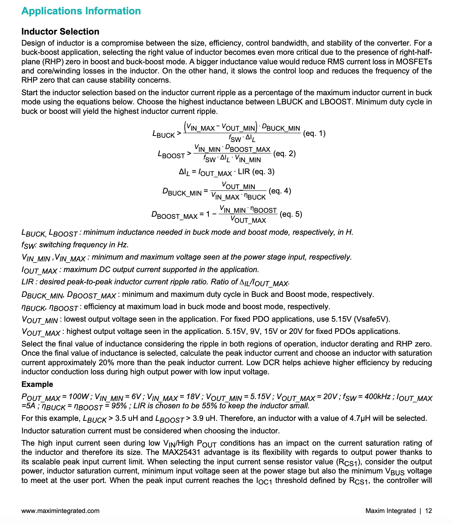
  • In the first image the inductor value is calculated from the max/min duty cycle in boost/buck modes respectively. In their equations the converter efficiency is used, and further down in the example it is selected as 95% on much more than inductance. The question is how this value is chose and other values, so why theyit is just throw this valuethrown like this? without any explanation.
  • Second question is why LIR is chosen to be so high? According to what I read online it is supposed to be around 30%.
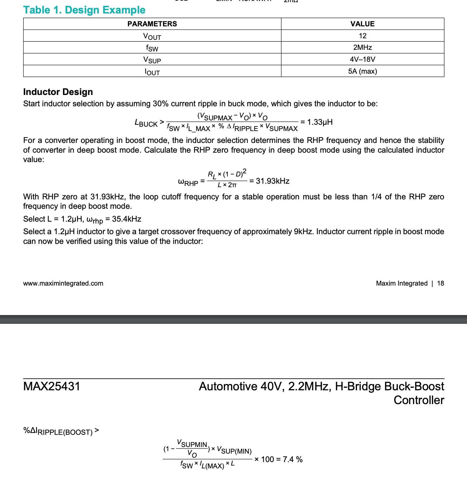
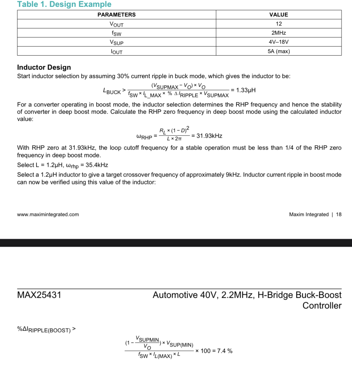
  • And the last question is why the 2nd example that they give on image 2 is really different from the 1st imagedesign example, and why only the Lbuck is calculated?

enter image description here1st image 2nd image

I am trying to design a project featuring MAX25431 buck-boost converter. After examining the datasheet I started the part selection for my application, but I have troubles understanding few details:

  • In the first image the inductor value is calculated from the max/min duty cycle in boost/buck modes respectively. In their equations the converter efficiency is used, and further down in the example it is selected as 95% on much more than inductance value and other values, so why they just throw this value like this?
  • Second question is why LIR is chosen to be so high? According to what I read online it is supposed to be around 30%.
  • And the last question is why the 2nd example that they give on image 2 is really different from 1st image?

enter image description here

I am trying to design a project featuring MAX25431 buck-boost converter. After examining the datasheet I started the part selection for my application, but I have troubles understanding few details:

  • In the first image the inductor value is calculated from the max/min duty cycle in boost/buck modes respectively. In their equations the converter efficiency is used, and further down in the example it is selected as 95%. The question is how this value is chose and why it is just thrown like this without any explanation.
  • Second question is why LIR is chosen to be so high? According to what I read online it is supposed to be around 30%.
  • And the last question is why the 2nd example that they give on image 2 is really different from the 1st design example, and why only the Lbuck is calculated?
1st image 2nd image

Post Closed as "Needs details or clarity" by Andy aka, ocrdu, colintd
Source Link
vorobey
  • 113
  • 8

How to understand MAX25431 datasheet on inductor selection?

I am trying to design a project featuring MAX25431 buck-boost converter. After examining the datasheet I started the part selection for my application, but I have troubles understanding few details:

  • In the first image the inductor value is calculated from the max/min duty cycle in boost/buck modes respectively. In their equations the converter efficiency is used, and further down in the example it is selected as 95% on much more than inductance value and other values, so why they just throw this value like this?
  • Second question is why LIR is chosen to be so high? According to what I read online it is supposed to be around 30%.
  • And the last question is why the 2nd example that they give on image 2 is really different from 1st image?

enter image description here