added 85 characters in body
Source Link

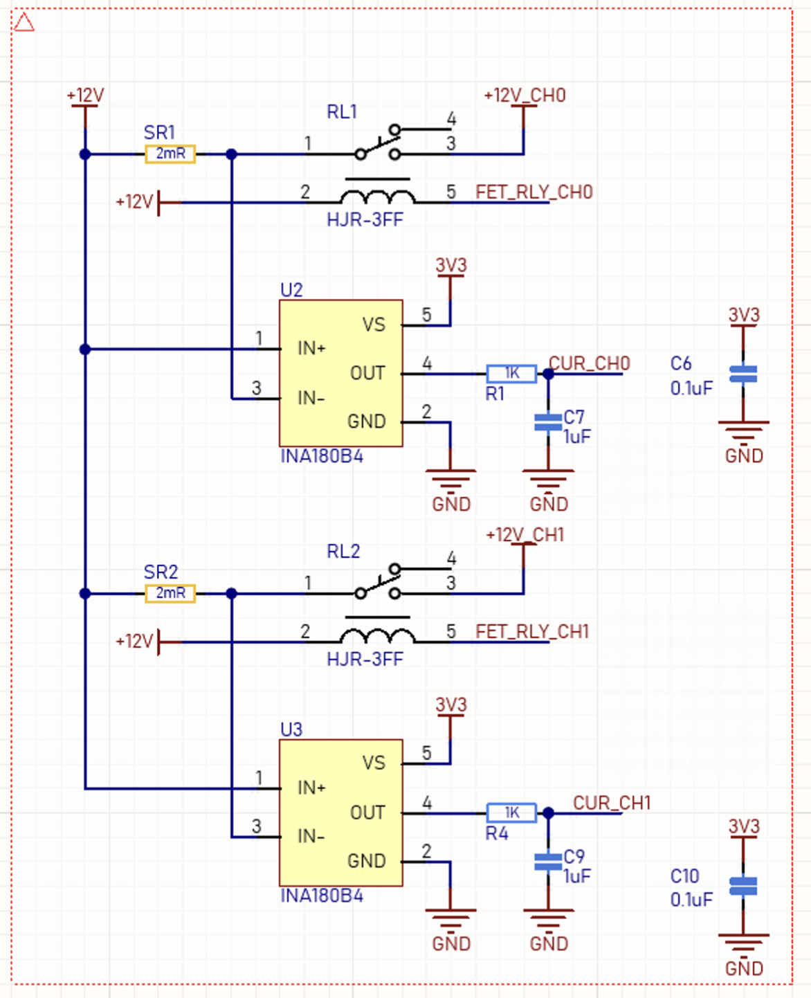
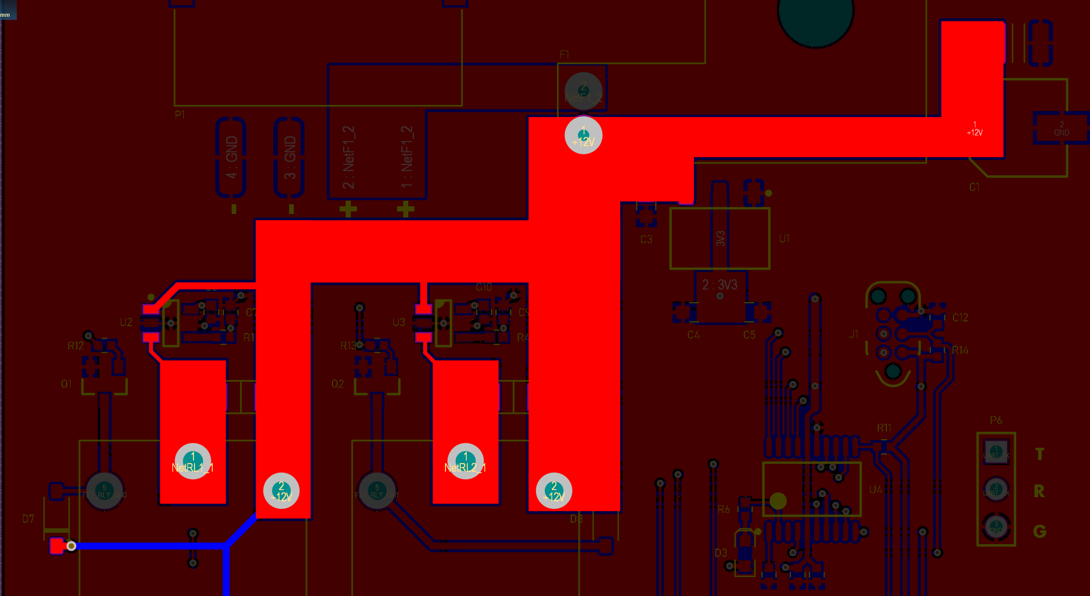
I've designed a two-channel current sensing circuit integrated into a board that outputs two separate signals. However, I'm encountering an issue where one channel seems to influence the other, which, to my understanding, should not happen.

Each channel in this circuit has its own current sensing component, but it appears that the operation of one channel is affecting the other. Additionally, I've observed that when there is no load connected to either channel, the circuit functions correctly. However, under load, the behavior changes.

Specifically, when a 5 A load is applied to only one channel, the voltage readings are as expected, but when one channel has a 5 A load and the other has a 1 A load, the voltage readings across the channels are not as expected. This discrepancy in voltage readings under different load conditions is puzzling.

I'm trying to figure out the root cause of this problem and understand why the voltage readings are affected in this way. Could this be a result of some form of interference, a design flaw in the circuit, or something else?

Furthermore, if there is a consistent relationship between the interactions of these two channels, I would like to know what formulas or calculations can be applied to predict or compensate for this influence.

Any insights or suggestions on how to diagnose and resolve this issue would be greatly appreciated.

enter image description here enter image description here

I've designed a two-channel current sensing circuit integrated into a board that outputs two separate signals. However, I'm encountering an issue where one channel seems to influence the other, which, to my understanding, should not happen.

Each channel in this circuit has its own current sensing component, but it appears that the operation of one channel is affecting the other. Additionally, I've observed that when there is no load connected to either channel, the circuit functions correctly. However, under load, the behavior changes.

Specifically, when a 5 A load is applied to only one channel, the voltage readings are as expected, but when one channel has a 5 A load and the other has a 1 A load, the voltage readings across the channels are not as expected. This discrepancy in voltage readings under different load conditions is puzzling.

I'm trying to figure out the root cause of this problem and understand why the voltage readings are affected in this way. Could this be a result of some form of interference, a design flaw in the circuit, or something else?

Furthermore, if there is a consistent relationship between the interactions of these two channels, I would like to know what formulas or calculations can be applied to predict or compensate for this influence.

Any insights or suggestions on how to diagnose and resolve this issue would be greatly appreciated.
enter image description here

I've designed a two-channel current sensing circuit integrated into a board that outputs two separate signals. However, I'm encountering an issue where one channel seems to influence the other, which, to my understanding, should not happen.

Each channel in this circuit has its own current sensing component, but it appears that the operation of one channel is affecting the other. Additionally, I've observed that when there is no load connected to either channel, the circuit functions correctly. However, under load, the behavior changes.

Specifically, when a 5 A load is applied to only one channel, the voltage readings are as expected, but when one channel has a 5 A load and the other has a 1 A load, the voltage readings across the channels are not as expected. This discrepancy in voltage readings under different load conditions is puzzling.

I'm trying to figure out the root cause of this problem and understand why the voltage readings are affected in this way. Could this be a result of some form of interference, a design flaw in the circuit, or something else?

Furthermore, if there is a consistent relationship between the interactions of these two channels, I would like to know what formulas or calculations can be applied to predict or compensate for this influence.

Any insights or suggestions on how to diagnose and resolve this issue would be greatly appreciated.

enter image description here enter image description here

added 5 characters in body; edited tags; edited title
Source Link
ocrdu
  • 9.3k
  • 23
  • 32
  • 42

Issue with Influence Between Channelsinfluence between channels in a Dualdual-Channel High Side Current Sensing Circuitchannel high-side current sensing circuit

I've designed a two-channel current sensing circuit integrated into a board that outputs two separate signals. However, I'm encountering an issue where one channel seems to influence the other, which, to my understanding, should not happen.

Each channel in this circuit has its own current sensing component, but it appears that the operation of one channel is affecting the other. Additionally, I've observed that when there is no load connected to either channel, the circuit functions correctly. However, under load, the behavior changes. 

Specifically, when a 5A5 A load is applied to only one channel, the voltage readings are as expected. But, but when one channel has a 5A5 A load and the other has a 1A1 A load, the voltage readings across the channels are not as expected. This discrepancy in voltage readings under different load conditions is puzzling.

I'm trying to figure out the root cause of this problem and understand why the voltage readings are affected in this way. Could this be a result of some form of interference, a design flaw in the circuit, or something else?

Furthermore, if there is a consistent relationship between the interactions of these two channels, I would like to know what formulas or calculations can be applied to predict or compensate for this influence.

Any insights or suggestions on how to diagnose and resolve this issue would be greatly appreciated.

enter image description here

Issue with Influence Between Channels in a Dual-Channel High Side Current Sensing Circuit

I've designed a two-channel current sensing circuit integrated into a board that outputs two separate signals. However, I'm encountering an issue where one channel seems to influence the other, which, to my understanding, should not happen.

Each channel in this circuit has its own current sensing component, but it appears that the operation of one channel is affecting the other. Additionally, I've observed that when there is no load connected to either channel, the circuit functions correctly. However, under load, the behavior changes. Specifically, when a 5A load is applied to only one channel, the voltage readings are as expected. But, when one channel has a 5A load and the other has a 1A load, the voltage readings across the channels are not as expected. This discrepancy in voltage readings under different load conditions is puzzling.

I'm trying to figure out the root cause of this problem and understand why the voltage readings are affected in this way. Could this be a result of some form of interference, a design flaw in the circuit, or something else?

Furthermore, if there is a consistent relationship between the interactions of these two channels, I would like to know what formulas or calculations can be applied to predict or compensate for this influence.

Any insights or suggestions on how to diagnose and resolve this issue would be greatly appreciated.

enter image description here

Issue with influence between channels in a dual-channel high-side current sensing circuit

I've designed a two-channel current sensing circuit integrated into a board that outputs two separate signals. However, I'm encountering an issue where one channel seems to influence the other, which, to my understanding, should not happen.

Each channel in this circuit has its own current sensing component, but it appears that the operation of one channel is affecting the other. Additionally, I've observed that when there is no load connected to either channel, the circuit functions correctly. However, under load, the behavior changes. 

Specifically, when a 5 A load is applied to only one channel, the voltage readings are as expected, but when one channel has a 5 A load and the other has a 1 A load, the voltage readings across the channels are not as expected. This discrepancy in voltage readings under different load conditions is puzzling.

I'm trying to figure out the root cause of this problem and understand why the voltage readings are affected in this way. Could this be a result of some form of interference, a design flaw in the circuit, or something else?

Furthermore, if there is a consistent relationship between the interactions of these two channels, I would like to know what formulas or calculations can be applied to predict or compensate for this influence.

Any insights or suggestions on how to diagnose and resolve this issue would be greatly appreciated.

enter image description here

deleted 39 characters in body
Source Link
toolic
  • 9.8k
  • 9
  • 27
  • 35

I've designed a two-channel current sensing circuit integrated into a board that outputs two separate signals. However, I'm encountering an issue where one channel seems to influence the other, which, to my understanding, should not happen.

Each channel in this circuit has its own current sensing component, but it appears that the operation of one channel is affecting the other. Additionally, I've observed that when there is no load connected to either channel, the circuit functions correctly. However, under load, the behavior changes. Specifically, when a 5A load is applied to only one channel, the voltage readings are as expected. But, when one channel has a 5A load and the other has a 1A load, the voltage readings across the channels are not as expected. This discrepancy in voltage readings under different load conditions is puzzling.

I'm trying to figure out the root cause of this problem and understand why the voltage readings are affected in this way. Could this be a result of some form of interference, a design flaw in the circuit, or something else?

Furthermore, if there is a consistent relationship between the interactions of these two channels, I would like to know what formulas or calculations can be applied to predict or compensate for this influence.

Any insights or suggestions on how to diagnose and resolve this issue would be greatly appreciated.

Thank you in advance for your help!

enter image description here

I've designed a two-channel current sensing circuit integrated into a board that outputs two separate signals. However, I'm encountering an issue where one channel seems to influence the other, which, to my understanding, should not happen.

Each channel in this circuit has its own current sensing component, but it appears that the operation of one channel is affecting the other. Additionally, I've observed that when there is no load connected to either channel, the circuit functions correctly. However, under load, the behavior changes. Specifically, when a 5A load is applied to only one channel, the voltage readings are as expected. But, when one channel has a 5A load and the other has a 1A load, the voltage readings across the channels are not as expected. This discrepancy in voltage readings under different load conditions is puzzling.

I'm trying to figure out the root cause of this problem and understand why the voltage readings are affected in this way. Could this be a result of some form of interference, a design flaw in the circuit, or something else?

Furthermore, if there is a consistent relationship between the interactions of these two channels, I would like to know what formulas or calculations can be applied to predict or compensate for this influence.

Any insights or suggestions on how to diagnose and resolve this issue would be greatly appreciated.

enter image description here

Source Link
Loading