added 955 characters in body
Source Link
bobflux
  • 81.6k
  • 3
  • 97
  • 236

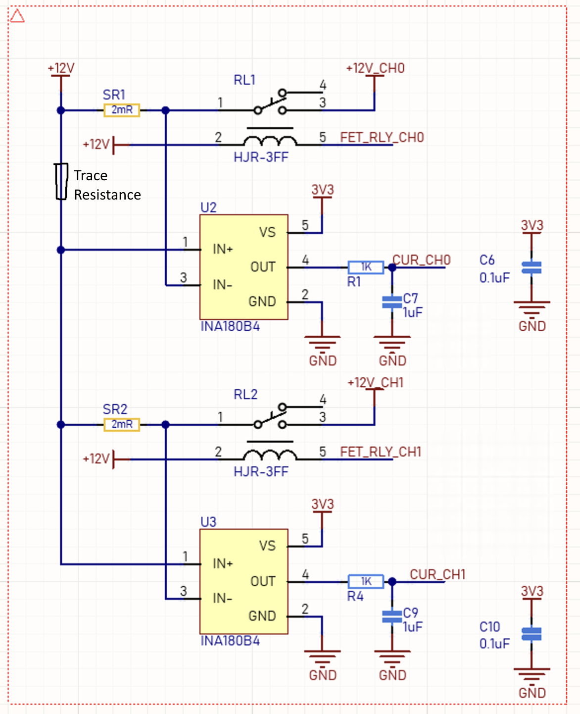
If the layout follows the schematic, current going to the output on the bottom creates a voltage drop on the trace resistance, which will be measured by U2.

enter image description here

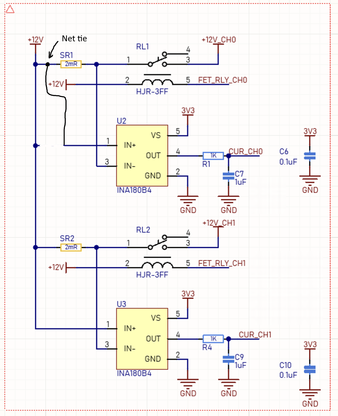
It should be routed like this instead, preferably with a note on the schematic.

enter image description here

If U2 is some distance away from SR1, then the two sense lines should be routed as a differential pair. To have the design rule check enforce it, you can put a net tie which makes the two sense lines into different nets from the power traces. This is especially useful if the power traces are copper pours, to prevent the sense lines from being connected to the wrong place.

Layout around the sense resistor is important for accuracy too.

EDIT:

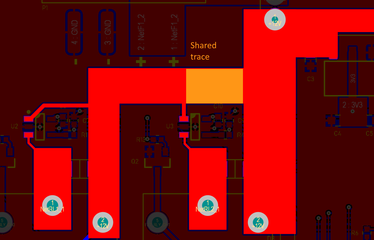
It would be useful to calculate the resistance of the shared trace:

enter image description here

Here's a trace resistance calculator. I can't see the dimensions, but you can get width and length easily from your layout software, and copper thickness from your fabrication specs.

It should be a good chunk of a milliohm... since your current sense resistors are only 2 mOhm, that would introduce a significant error.

Likewise, since your sense traces do not go to the 2mOhm resistors, but to the power traces some distance away from the resistors, the effective resistance value should be higher than 2 mOhm. So your current sense amps should have higher gain than intended. Maybe =50%...+100% gain error, but I have no idea what copper thickness you used, so it may be different.

Knowing the trace resistance, you can calculate how much error should result (both on the gain and on crosstalk) and check the readings to confirm.

On the prototype board you can cut the sense traces and replace them with hand soldered wrapping wire, soldered directly between the inputs of the sense amps and both ends of the current sense resistors. If that solves the problem, you know what to do for the next layout revision.

I don't see the filter caps C7/C9 on the layout... they should be close to the ADC's ground pin. If current flows in your ground plane, that will create voltage drops, so "ground" is not at the same potential everywhere. The current sense amps output a "ground"-reference voltage, but the reference they use is their own ground pin, wherever it is on the board. So if that "ground" is not the same potential as "ground" the ADC uses as 0 Volts reference, you have a bit of extra noise. It's the same for the capacitors, if your filter cap is on a noisy part of the ground plane, like near power devices or DC-DC converters, it will inject the ground noise into the signal it's supposed to filter.

If the layout follows the schematic, current going to the output on the bottom creates a voltage drop on the trace resistance, which will be measured by U2.

enter image description here

It should be routed like this instead, preferably with a note on the schematic.

enter image description here

If U2 is some distance away from SR1, then the two sense lines should be routed as a differential pair. To have the design rule check enforce it, you can put a net tie which makes the two sense lines into different nets from the power traces. This is especially useful if the power traces are copper pours, to prevent the sense lines from being connected to the wrong place.

Layout around the sense resistor is important for accuracy too.

EDIT:

It would be useful to calculate the resistance of the shared trace:

enter image description here

Here's a trace resistance calculator. I can't see the dimensions, but you can get width and length easily from your layout software, and copper thickness from your fabrication specs.

It should be a good chunk of a milliohm... since your current sense resistors are only 2 mOhm, that would introduce a significant error.

Likewise, since your sense traces do not go to the 2mOhm resistors, but to the power traces some distance away from the resistors, the effective resistance value should be higher than 2 mOhm. So your current sense amps should have higher gain than intended.

Knowing the trace resistance, you can calculate how much error should result (both on the gain and on crosstalk) and check the readings to confirm.

On the prototype board you can cut the sense traces and replace them with hand soldered wrapping wire, soldered directly between the inputs of the sense amps and both ends of the current sense resistors. If that solves the problem, you know what to do for the next layout revision.

If the layout follows the schematic, current going to the output on the bottom creates a voltage drop on the trace resistance, which will be measured by U2.

enter image description here

It should be routed like this instead, preferably with a note on the schematic.

enter image description here

If U2 is some distance away from SR1, then the two sense lines should be routed as a differential pair. To have the design rule check enforce it, you can put a net tie which makes the two sense lines into different nets from the power traces. This is especially useful if the power traces are copper pours, to prevent the sense lines from being connected to the wrong place.

Layout around the sense resistor is important for accuracy too.

EDIT:

It would be useful to calculate the resistance of the shared trace:

enter image description here

Here's a trace resistance calculator. I can't see the dimensions, but you can get width and length easily from your layout software, and copper thickness from your fabrication specs.

It should be a good chunk of a milliohm... since your current sense resistors are only 2 mOhm, that would introduce a significant error.

Likewise, since your sense traces do not go to the 2mOhm resistors, but to the power traces some distance away from the resistors, the effective resistance value should be higher than 2 mOhm. So your current sense amps should have higher gain than intended. Maybe =50%...+100% gain error, but I have no idea what copper thickness you used, so it may be different.

Knowing the trace resistance, you can calculate how much error should result (both on the gain and on crosstalk) and check the readings to confirm.

On the prototype board you can cut the sense traces and replace them with hand soldered wrapping wire, soldered directly between the inputs of the sense amps and both ends of the current sense resistors. If that solves the problem, you know what to do for the next layout revision.

I don't see the filter caps C7/C9 on the layout... they should be close to the ADC's ground pin. If current flows in your ground plane, that will create voltage drops, so "ground" is not at the same potential everywhere. The current sense amps output a "ground"-reference voltage, but the reference they use is their own ground pin, wherever it is on the board. So if that "ground" is not the same potential as "ground" the ADC uses as 0 Volts reference, you have a bit of extra noise. It's the same for the capacitors, if your filter cap is on a noisy part of the ground plane, like near power devices or DC-DC converters, it will inject the ground noise into the signal it's supposed to filter.
added 955 characters in body
Source Link
bobflux
  • 81.6k
  • 3
  • 97
  • 236

If the layout follows the schematic, current going to the output on the bottom creates a voltage drop on the trace resistance, which will be measured by U2.

enter image description here

It should be routed like this instead, preferably with a note on the schematic.

enter image description here

If U2 is some distance away from SR1, then the two sense lines should be routed as a differential pair. To have the design rule check enforce it, you can put a net tie which makes the two sense lines into different nets from the power traces. This is especially useful if the power traces are copper pours, to prevent the sense lines from being connected to the wrong place.

Layout around the sense resistor is important for accuracy too.

EDIT:

It would be useful to calculate the resistance of the shared trace:

enter image description here

Here's a trace resistance calculator. I can't see the dimensions, but you can get width and length easily from your layout software, and copper thickness from your fabrication specs.

It should be a good chunk of a milliohm... since your current sense resistors are only 2 mOhm, that would introduce a significant error.

Likewise, since your sense traces do not go to the 2mOhm resistors, but to the power traces some distance away from the resistors, the effective resistance value should be higher than 2 mOhm. So your current sense amps should have higher gain than intended.

Knowing the trace resistance, you can calculate how much error should result (both on the gain and on crosstalk) and check the readings to confirm.

On the prototype board you can cut the sense traces and replace them with hand soldered wrapping wire, soldered directly between the inputs of the sense amps and both ends of the current sense resistors. If that solves the problem, you know what to do for the next layout revision.

If the layout follows the schematic, current going to the output on the bottom creates a voltage drop on the trace resistance, which will be measured by U2.

enter image description here

It should be routed like this instead, preferably with a note on the schematic.

enter image description here

If U2 is some distance away from SR1, then the two sense lines should be routed as a differential pair. To have the design rule check enforce it, you can put a net tie which makes the two sense lines into different nets from the power traces. This is especially useful if the power traces are copper pours, to prevent the sense lines from being connected to the wrong place.

Layout around the sense resistor is important for accuracy too.

EDIT:

It would be useful to calculate the resistance of the shared trace:

enter image description here

Here's a trace resistance calculator. I can't see the dimensions, but you can get width and length easily from your layout software, and copper thickness from your fabrication specs.

It should be a good chunk of a milliohm... since your current sense resistors are only 2 mOhm, that would introduce a significant error.

Likewise, since your sense traces do not go to the 2mOhm resistors, but to the power traces some distance away from the resistors, the effective resistance value should be higher than 2 mOhm. So your current sense amps should have higher gain than intended.

Knowing the trace resistance, you can calculate how much error should result (both on the gain and on crosstalk) and check the readings to confirm.

On the prototype board you can cut the sense traces and replace them with hand soldered wrapping wire, soldered directly between the inputs of the sense amps and both ends of the current sense resistors. If that solves the problem, you know what to do for the next layout revision.

Source Link
bobflux
  • 81.6k
  • 3
  • 97
  • 236

If the layout follows the schematic, current going to the output on the bottom creates a voltage drop on the trace resistance, which will be measured by U2.

enter image description here

It should be routed like this instead, preferably with a note on the schematic.

enter image description here

If U2 is some distance away from SR1, then the two sense lines should be routed as a differential pair. To have the design rule check enforce it, you can put a net tie which makes the two sense lines into different nets from the power traces. This is especially useful if the power traces are copper pours, to prevent the sense lines from being connected to the wrong place.

Layout around the sense resistor is important for accuracy too.