Kelvinhertz -> kilohertz
Source Link
winny
  • 16.8k
  • 6
  • 50
  • 71

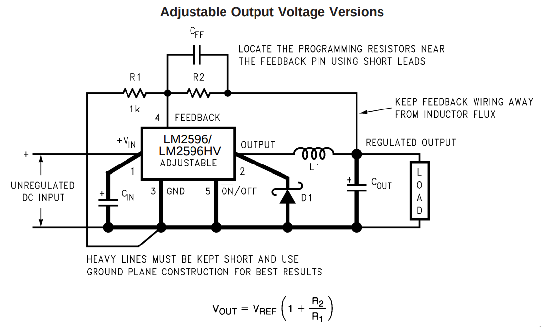
I am trying to replace R2 from this LM2596-based module for a MOSFET-based variable resistor:

enter image description here

According to this answer (https://electronics.stackexchange.com/a/15273/148272) it may be possible to use a low frequency PWM signal to vary resistance by varying the duty cycle.

My goal is to use an Arduino's relatively low PWM freq (~500 Hz) to achieve this and get rid of the pot.

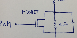
Other than just removing the trimmer I think I also need to remove \$C_{FF}\$ as per the info from this other question (PWM controlled variable resistance):

enter image description here

As shown, the job of the capacitor is to destroy the MOSFET. ie it is incorrectly shown.

Since the LM2596 works on the basis of very quickly (150 KHzkHz) comparing the reference voltage (between R1 and R2) and adjusting the duty cycle so \$V_{OUT}\$ approaches the desired voltage, by switching R2 on and off the average resistance \$R_{AVG}=\frac{R}{D}\$ should do the trick, I think.

Would this work?

Other solutions I have explored include:

  • Turning the MOSFET into a variable resistor by operating it in the Ohmic region, by low-pass filtering the PWM signal to get a suitable DC for the gate. This dissipates a lot of power and might not even be that reliable, from other comments I keep reading around. Also JFETs are apparently more suited for this and I don't have any at hand to try.
  • Use an R-2R Resistive Ladder Network and use the Nano to select the desired R2. This works but is kinda wasteful.
  • Amplifying the PWM signal using a power MOSFET and low-pass filtering the output to DC. The problem with this is that for higher loads I will need to get a big (and costly) resistance (at least 6 W for my application) or putting a LOT (like 24) 0.25 W resistances in parallel to allow for a bigger load.

The load is a BLDC fan rated at 12V 0.5A, btw.

I am trying to replace R2 from this LM2596-based module for a MOSFET-based variable resistor:

enter image description here

According to this answer (https://electronics.stackexchange.com/a/15273/148272) it may be possible to use a low frequency PWM signal to vary resistance by varying the duty cycle.

My goal is to use an Arduino's relatively low PWM freq (~500 Hz) to achieve this and get rid of the pot.

Other than just removing the trimmer I think I also need to remove \$C_{FF}\$ as per the info from this other question (PWM controlled variable resistance):

enter image description here

As shown, the job of the capacitor is to destroy the MOSFET. ie it is incorrectly shown.

Since the LM2596 works on the basis of very quickly (150 KHz) comparing the reference voltage (between R1 and R2) and adjusting the duty cycle so \$V_{OUT}\$ approaches the desired voltage, by switching R2 on and off the average resistance \$R_{AVG}=\frac{R}{D}\$ should do the trick, I think.

Would this work?

Other solutions I have explored include:

  • Turning the MOSFET into a variable resistor by operating it in the Ohmic region, by low-pass filtering the PWM signal to get a suitable DC for the gate. This dissipates a lot of power and might not even be that reliable, from other comments I keep reading around. Also JFETs are apparently more suited for this and I don't have any at hand to try.
  • Use an R-2R Resistive Ladder Network and use the Nano to select the desired R2. This works but is kinda wasteful.
  • Amplifying the PWM signal using a power MOSFET and low-pass filtering the output to DC. The problem with this is that for higher loads I will need to get a big (and costly) resistance (at least 6 W for my application) or putting a LOT (like 24) 0.25 W resistances in parallel to allow for a bigger load.

The load is a BLDC fan rated at 12V 0.5A, btw.
I am trying to replace R2 from this LM2596-based module for a MOSFET-based variable resistor:

enter image description here

According to this answer (https://electronics.stackexchange.com/a/15273/148272) it may be possible to use a low frequency PWM signal to vary resistance by varying the duty cycle.

My goal is to use an Arduino's relatively low PWM freq (~500 Hz) to achieve this and get rid of the pot.

Other than just removing the trimmer I think I also need to remove \$C_{FF}\$ as per the info from this other question (PWM controlled variable resistance):

enter image description here

As shown, the job of the capacitor is to destroy the MOSFET. ie it is incorrectly shown.

Since the LM2596 works on the basis of very quickly (150 kHz) comparing the reference voltage (between R1 and R2) and adjusting the duty cycle so \$V_{OUT}\$ approaches the desired voltage, by switching R2 on and off the average resistance \$R_{AVG}=\frac{R}{D}\$ should do the trick, I think.

Would this work?

Other solutions I have explored include:

  • Turning the MOSFET into a variable resistor by operating it in the Ohmic region, by low-pass filtering the PWM signal to get a suitable DC for the gate. This dissipates a lot of power and might not even be that reliable, from other comments I keep reading around. Also JFETs are apparently more suited for this and I don't have any at hand to try.
  • Use an R-2R Resistive Ladder Network and use the Nano to select the desired R2. This works but is kinda wasteful.
  • Amplifying the PWM signal using a power MOSFET and low-pass filtering the output to DC. The problem with this is that for higher loads I will need to get a big (and costly) resistance (at least 6 W for my application) or putting a LOT (like 24) 0.25 W resistances in parallel to allow for a bigger load.

The load is a BLDC fan rated at 12V 0.5A, btw.
deleted 23 characters in body
Source Link

I am trying to replace R2 from this LM2596-based module for a MOSFET-based variable resistor:

enter image description here

According to this answer (https://electronics.stackexchange.com/a/15273/148272) it may be possible to use a low frequency PWM signal to vary resistance by varying the duty cycle.

My goal is to use an Arduino's relatively low PWM freq (~500 Hz) to achieve this and get rid of the pot.

Other than just removing the trimmer I think I also need to remove \$C_{FF}\$ as per the info from this other question (PWM controlled variable resistance):

enter image description here

As shown, the job of the capacitor is to destroy the MOSFET. ie it is incorrectly shown.

Since the LM2596 works on the basis of very quickly (150 KHz) comparing the reference voltage (between R1 and R2) and adjusting the duty cycle so \$V_{OUT}\$ approaches the desired voltage, by switching R2 on and off the average resistance \$R_{AVG}=\frac{R}{D}\$ should do the trick, I think.

Would this work?

Other solutions I have explored include:

  • Turning the MOSFET into a variable resistor by operating it in the Ohmic region, by low-pass filtering the PWM signal to get a suitable DC for the gate. This dissipates a lot of power and might not even be that reliable, from other comments I keep reading around. Also JFETs are apparently more suited for this and I don't have any at hand to try.
  • Use a bunch of FETs in parallel with a bunch of resistancesan R-2R Resistive Ladder Network and use the Nano to select the desired R2. This works but is kinda wasteful.
  • Amplifying the PWM signal using a power MOSFET and low-pass filtering the output to DC. The problem with this is that for higher loads I will need to get a big (and costly) resistance (at least 6 W for my application) or putting a LOT (like 24) 0.25 W resistances in parallel to allow for a bigger load.

The load is a BLDC fan rated at 12V 0.5A, btw.

I am trying to replace R2 from this LM2596-based module for a MOSFET-based variable resistor:

enter image description here

According to this answer (https://electronics.stackexchange.com/a/15273/148272) it may be possible to use a low frequency PWM signal to vary resistance by varying the duty cycle.

My goal is to use an Arduino's relatively low PWM freq (~500 Hz) to achieve this and get rid of the pot.

Other than just removing the trimmer I think I also need to remove \$C_{FF}\$ as per the info from this other question (PWM controlled variable resistance):

enter image description here

As shown, the job of the capacitor is to destroy the MOSFET. ie it is incorrectly shown.

Since the LM2596 works on the basis of very quickly (150 KHz) comparing the reference voltage (between R1 and R2) and adjusting the duty cycle so \$V_{OUT}\$ approaches the desired voltage, by switching R2 on and off the average resistance \$R_{AVG}=\frac{R}{D}\$ should do the trick, I think.

Would this work?

Other solutions I have explored include:

  • Turning the MOSFET into a variable resistor by operating it in the Ohmic region, by low-pass filtering the PWM signal to get a suitable DC for the gate. This dissipates a lot of power and might not even be that reliable, from other comments I keep reading around. Also JFETs are apparently more suited for this and I don't have any at hand to try.
  • Use a bunch of FETs in parallel with a bunch of resistances and use the Nano to select the desired R2. This works but is kinda wasteful.
  • Amplifying the PWM signal using a power MOSFET and low-pass filtering the output to DC. The problem with this is that for higher loads I will need to get a big (and costly) resistance (at least 6 W for my application) or putting a LOT (like 24) 0.25 W resistances in parallel to allow for a bigger load.

The load is a BLDC fan rated at 12V 0.5A, btw.

I am trying to replace R2 from this LM2596-based module for a MOSFET-based variable resistor:

enter image description here

According to this answer (https://electronics.stackexchange.com/a/15273/148272) it may be possible to use a low frequency PWM signal to vary resistance by varying the duty cycle.

My goal is to use an Arduino's relatively low PWM freq (~500 Hz) to achieve this and get rid of the pot.

Other than just removing the trimmer I think I also need to remove \$C_{FF}\$ as per the info from this other question (PWM controlled variable resistance):

enter image description here

As shown, the job of the capacitor is to destroy the MOSFET. ie it is incorrectly shown.

Since the LM2596 works on the basis of very quickly (150 KHz) comparing the reference voltage (between R1 and R2) and adjusting the duty cycle so \$V_{OUT}\$ approaches the desired voltage, by switching R2 on and off the average resistance \$R_{AVG}=\frac{R}{D}\$ should do the trick, I think.

Would this work?

Other solutions I have explored include:

  • Turning the MOSFET into a variable resistor by operating it in the Ohmic region, by low-pass filtering the PWM signal to get a suitable DC for the gate. This dissipates a lot of power and might not even be that reliable, from other comments I keep reading around. Also JFETs are apparently more suited for this and I don't have any at hand to try.
  • Use an R-2R Resistive Ladder Network and use the Nano to select the desired R2. This works but is kinda wasteful.
  • Amplifying the PWM signal using a power MOSFET and low-pass filtering the output to DC. The problem with this is that for higher loads I will need to get a big (and costly) resistance (at least 6 W for my application) or putting a LOT (like 24) 0.25 W resistances in parallel to allow for a bigger load.

The load is a BLDC fan rated at 12V 0.5A, btw.

Source Link

Use MOSFET as low frequency PWM variable resistor for step down regulator

I am trying to replace R2 from this LM2596-based module for a MOSFET-based variable resistor:

enter image description here

According to this answer (https://electronics.stackexchange.com/a/15273/148272) it may be possible to use a low frequency PWM signal to vary resistance by varying the duty cycle.

My goal is to use an Arduino's relatively low PWM freq (~500 Hz) to achieve this and get rid of the pot.

Other than just removing the trimmer I think I also need to remove \$C_{FF}\$ as per the info from this other question (PWM controlled variable resistance):

enter image description here

As shown, the job of the capacitor is to destroy the MOSFET. ie it is incorrectly shown.

Since the LM2596 works on the basis of very quickly (150 KHz) comparing the reference voltage (between R1 and R2) and adjusting the duty cycle so \$V_{OUT}\$ approaches the desired voltage, by switching R2 on and off the average resistance \$R_{AVG}=\frac{R}{D}\$ should do the trick, I think.

Would this work?

Other solutions I have explored include:

  • Turning the MOSFET into a variable resistor by operating it in the Ohmic region, by low-pass filtering the PWM signal to get a suitable DC for the gate. This dissipates a lot of power and might not even be that reliable, from other comments I keep reading around. Also JFETs are apparently more suited for this and I don't have any at hand to try.
  • Use a bunch of FETs in parallel with a bunch of resistances and use the Nano to select the desired R2. This works but is kinda wasteful.
  • Amplifying the PWM signal using a power MOSFET and low-pass filtering the output to DC. The problem with this is that for higher loads I will need to get a big (and costly) resistance (at least 6 W for my application) or putting a LOT (like 24) 0.25 W resistances in parallel to allow for a bigger load.

The load is a BLDC fan rated at 12V 0.5A, btw.