Became Hot Network Question
deleted 4 characters in body
Source Link
tampler
  • 109
  • 9

I wanted to design a small temperature-regulated DC heater for the sake of educational purposes in the field of control theory.

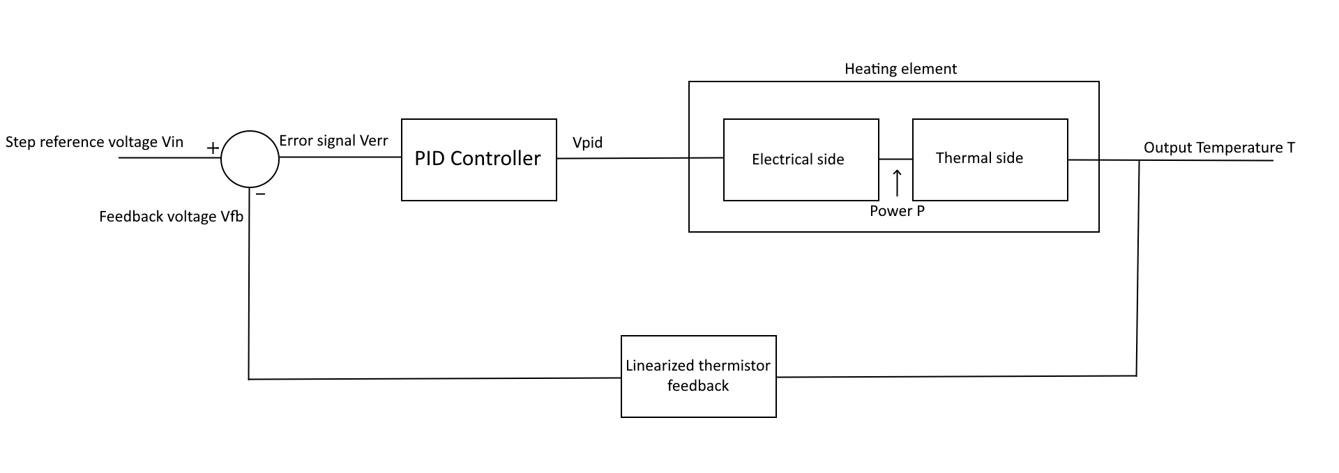
The idea is to heat up a resistive element through a buck converter of some sorts and to regulate that with a control loop involving a PID controller for the controller and a linearized thermistor for the feedback, like pictured in the following block diagram:

enter image description here

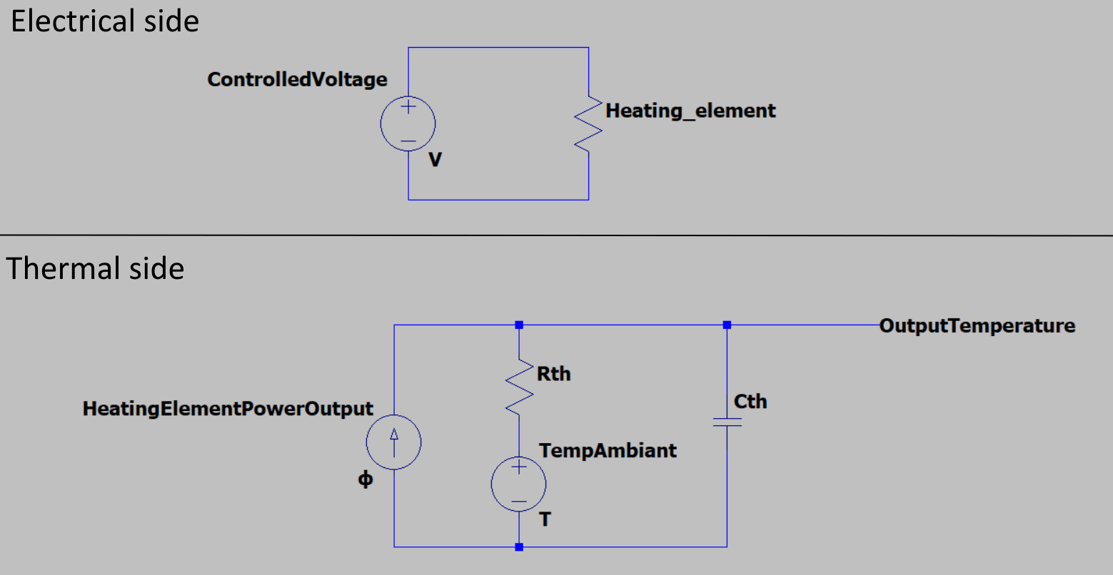
I naturally wanted to first analytically find the transfer function of that heating system which incorporates both electrical and thermal equations, the schematic of the system I came up with looks like the following:

enter image description here

Please note that for the sake of simplicity:

  1. I am oversimplifying the electrical side, "ControlledVoltage" should eventually be driven by a buck converter but as this isn't related to my current issue I'll assume that it is directly proportional to the output voltage of the PID controller ("Vpid").
  2. For the thermal side I'm using the thermal-electrical analogy to model the thermal behavior of the heating system through an electrical circuit

So, it should be easy to find the transfer function of the thermal side as it's nothing more than an equivalent RC circuit with the thermal flux ϕ as an input and the temperature of the heating system as an output.

However, when attempting to find the transfer function of the electrical side with the controlled voltage as an input and the dissipated power in the resistor as an output, I obviously find:

$$P = \frac{V^2}{R}$$

Which is a non-linear equation, which is also a huge problem since transfer functions are by definition linear time-invariant systems, meaning that I cannot use this equation to model my transfer function or that I need to find some way around it.

So my question might appear obvious now, but how can I find the transfer function of my system? I am obviously not the first person in the world to attempt to design a regulated DC heater and as such probably also not the first one to stumble across this issue, is there some tricks to linearize the system, some equations I missed, something I simply didn't understand about transfer functions, or maybe an entirely different design philosophy I missed?

Please note that I am aware that I could build the system, find the impulse response experimentally, curve-fit it and eventually find the transfer function. But again, I'm doing this little project for educational purposes and I would greatly appreciate finding the transfer function analytically.

Any help would be greatly appreciated.
I wanted to design a small temperature-regulated DC heater for the sake of educational purposes in the field of control theory.

The idea is to heat up a resistive element through a buck converter of some sorts and to regulate that with a control loop involving a PID controller for the controller and a linearized thermistor for the feedback, like pictured in the following block diagram:

enter image description here

I naturally wanted to first analytically find the transfer function of that heating system which incorporates both electrical and thermal equations, the schematic of the system I came up with looks like the following:

enter image description here

Please note that for the sake of simplicity:

  1. I am oversimplifying the electrical side, "ControlledVoltage" should eventually be driven by a buck converter but as this isn't related to my current issue I'll assume that it is directly proportional to the output voltage of the PID controller ("Vpid").
  2. For the thermal side I'm using the thermal-electrical analogy to model the thermal behavior of the heating system through an electrical circuit

So, it should be easy to find the transfer function of the thermal side as it's nothing more than an equivalent RC circuit with the thermal flux ϕ as an input and the temperature of the heating system as an output.

However, when attempting to find the transfer function of the electrical side with the controlled voltage as an input and the dissipated power in the resistor as an output, I obviously find:

$$P = \frac{V^2}{R}$$

Which is a non-linear equation, which is also a huge problem since transfer functions are by definition linear time-invariant systems, meaning that I cannot use this equation to model my transfer function or that I need to find some way around it.

So my question might appear obvious now, how can I find the transfer function of my system? I am obviously not the first person in the world to attempt to design a regulated DC heater and as such probably also not the first one to stumble across this issue, is there some tricks to linearize the system, some equations I missed, something I simply didn't understand about transfer functions, or maybe an entirely different design philosophy I missed?

Please note that I am aware that I could build the system, find the impulse response experimentally, curve-fit it and eventually find the transfer function. But again, I'm doing this little project for educational purposes and I would greatly appreciate finding the transfer function analytically.

Any help would be greatly appreciated.
No space before colon in English
Source Link
winny
  • 16.8k
  • 6
  • 50
  • 71

I wanted to design a small temperature-regulated DC heater for the sake of educational purposes in the field of control theory.

The idea is to heat up a resistive element through a buck converter of some sorts and to regulate that with a control loop involving a PID controller for the controller and a linearized thermistor for the feedback, like pictured in the following block diagram  :

enter image description here

I naturally wanted to first analytically find the transfer function of that heating system which incorporates both electrical and thermal equations, the schematic of the system I came up with looks like the following  :

enter image description here

Please note that for the sake of simplicity  :

  1. I am oversimplifying the electrical side, "ControlledVoltage" should eventually be driven by a buck converter but as this isn't related to my current issue I'll assume that it is directly proportional to the output voltage of the PID controller ("Vpid").
  2. For the thermal side I'm using the thermal-electrical analogy to model the thermal behavior of the heating system through an electrical circuit

So, it should be easy to find the transfer function of the thermal side as it's nothing more than an equivalent RC circuit with the thermal flux ϕ as an input and the temperature of the heating system as an output.

However, when attempting to find the transfer function of the electrical side with the controlled voltage as an input and the dissipated power in the resistor as an output, I obviously find:

$$P = \frac{V^2}{R}$$

Which is a non-linear equation, which is also a huge problem since transfer functions are by definition linear time-invariant systems, meaning that I cannot use this equation to model my transfer function or that I need to find some way around it.

So my question might appear obvious now, but how can I find the transfer function of my system? I am obviously not the first person in the world to attempt to design a regulated DC heater and as such probably also not the first one to stumble across this issue, is there some tricks to linearize the system, some equations I missed, something I simply didn't understand about transfer functions, or maybe an entirely different design philosophy I missed?

Please note that I am aware that I could build the system, find the impulse response experimentally, curve-fit it and eventually find the transfer function. But again, I'm doing this little project for educational purposes and I would greatly appreciate finding the transfer function analytically.

Any help would be greatly appreciated.

I wanted to design a small temperature-regulated DC heater for the sake of educational purposes in the field of control theory.

The idea is to heat up a resistive element through a buck converter of some sorts and to regulate that with a control loop involving a PID controller for the controller and a linearized thermistor for the feedback, like pictured in the following block diagram:

enter image description here

I naturally wanted to first analytically find the transfer function of that heating system which incorporates both electrical and thermal equations, the schematic of the system I came up with looks like the following:

enter image description here

Please note that for the sake of simplicity:

  1. I am oversimplifying the electrical side, "ControlledVoltage" should eventually be driven by a buck converter but as this isn't related to my current issue I'll assume that it is directly proportional to the output voltage of the PID controller ("Vpid").
  2. For the thermal side I'm using the thermal-electrical analogy to model the thermal behavior of the heating system through an electrical circuit

So, it should be easy to find the transfer function of the thermal side as it's nothing more than an equivalent RC circuit with the thermal flux ϕ as an input and the temperature of the heating system as an output.

However, when attempting to find the transfer function of the electrical side with the controlled voltage as an input and the dissipated power in the resistor as an output, I obviously find:

$$P = \frac{V^2}{R}$$

Which is a non-linear equation, which is also a huge problem since transfer functions are by definition linear time-invariant systems, meaning that I cannot use this equation to model my transfer function or that I need to find some way around it.

So my question might appear obvious now, but how can I find the transfer function of my system? I am obviously not the first person in the world to attempt to design a regulated DC heater and as such probably also not the first one to stumble across this issue, is there some tricks to linearize the system, some equations I missed, something I simply didn't understand about transfer functions, or maybe an entirely different design philosophy I missed?

Please note that I am aware that I could build the system, find the impulse response experimentally, curve-fit it and eventually find the transfer function. But again, I'm doing this little project for educational purposes and I would greatly appreciate finding the transfer function analytically.

Any help would be greatly appreciated.

Source Link
tampler
  • 109
  • 9

Transfer function of a heating system

I wanted to design a small temperature-regulated DC heater for the sake of educational purposes in the field of control theory.

The idea is to heat up a resistive element through a buck converter of some sorts and to regulate that with a control loop involving a PID controller for the controller and a linearized thermistor for the feedback, like pictured in the following block diagram :

enter image description here

I naturally wanted to first analytically find the transfer function of that heating system which incorporates both electrical and thermal equations, the schematic of the system I came up with looks like the following :

enter image description here

Please note that for the sake of simplicity :

  1. I am oversimplifying the electrical side, "ControlledVoltage" should eventually be driven by a buck converter but as this isn't related to my current issue I'll assume that it is directly proportional to the output voltage of the PID controller ("Vpid").
  2. For the thermal side I'm using the thermal-electrical analogy to model the thermal behavior of the heating system through an electrical circuit

So, it should be easy to find the transfer function of the thermal side as it's nothing more than an equivalent RC circuit with the thermal flux ϕ as an input and the temperature of the heating system as an output.

However, when attempting to find the transfer function of the electrical side with the controlled voltage as an input and the dissipated power in the resistor as an output, I obviously find:

$$P = \frac{V^2}{R}$$

Which is a non-linear equation, which is also a huge problem since transfer functions are by definition linear time-invariant systems, meaning that I cannot use this equation to model my transfer function or that I need to find some way around it.

So my question might appear obvious now, but how can I find the transfer function of my system? I am obviously not the first person in the world to attempt to design a regulated DC heater and as such probably also not the first one to stumble across this issue, is there some tricks to linearize the system, some equations I missed, something I simply didn't understand about transfer functions, or maybe an entirely different design philosophy I missed?

Please note that I am aware that I could build the system, find the impulse response experimentally, curve-fit it and eventually find the transfer function. But again, I'm doing this little project for educational purposes and I would greatly appreciate finding the transfer function analytically.

Any help would be greatly appreciated.