I'm trying to adapt a current limiter design that I found, and I'm having trouble understanding the "current sense" part of it.
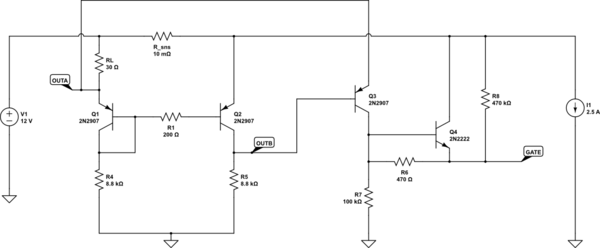
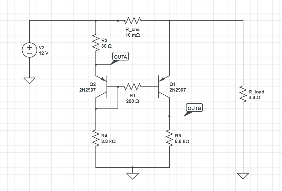
The current sensing is implemented using a shunt resistor, which is then measured using a current mirror using the circuit below.

simulate this circuit – Schematic created using CircuitLab
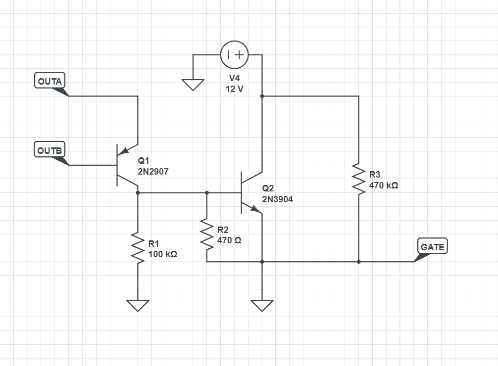
The designated output nodes (OUTA, OUTB) are then fed into a simple amplifier, which in turn drives the a high-side PMOS FET gate (GATE).
In theory this circuit should allow current to pass up-to a limit that is set by R2RL, and afterwards put the high-side FET into linear region to limit the current.
I'm trying to understand how the current sense part of this circuit works, and how one would analyze and select the resistor values for a given current limit, input voltage, etc.
Most of the designs for current sensing using a current mirror I've seen employ a emitter resistor on Q1 (e.g. 1), which is used to set the quiescent current based on the maximum sense voltage deviation, but this design does not have this so I'm having trouble to start with the analysis.
Any pointers would be highly appreciated.
EDIT: updated schematics to fix gate short and provide easy simulation


