deleted 1 character in body; edited tags; edited title
Source Link
ocrdu
  • 9.3k
  • 23
  • 32
  • 42

high gain High-gain transimpedance amplifier with photodiode not functioning as expected

I am designing a trans-impedance amplifier using a TEMD7000X01 photodiode(TEMD7000X01) and thean AD8551ARZ OPAMPop-amp. The RFRF is 100k ohms100 kΩ, CFCF is 150 pF, and VccVCC is +3.3 V. The output of the OPAMPop-amp is being fedconnected to an ADC pin of a microcontroller. 

This circuit works as intended when the OPAMPop-amp is on. However, but when it is off, because the diode is forward-biased, the voltage at the output is negative, which is an issue for our microcontroller. Adding a small signal diode at the output does help limit the negative voltage, but there is some leakage current which is not ideal. 

I had thought that if the photodiode was reverse-biased instead, it would fix the negative voltage issue when the OPAMPop-amp is off. This does fix the negative voltage issue when the OPAMPop-amp is off, but when it is on, the output is stuck at 0. Any advice on how to manipulate the circuit to fix the negative voltage issue? thanks!

enter image description here

high gain transimpedance amplifier with photodiode not functioning as expected

I am designing a trans-impedance amplifier using a photodiode(TEMD7000X01) and the AD8551ARZ OPAMP. The RF is 100k ohms, CF is 150 pF, and Vcc is +3.3 V. The output of the OPAMP is being fed to an ADC pin of a microcontroller. This circuit works as intended when the OPAMP is on. However, when it is off, because the diode is forward-biased, the voltage at the output is negative, which is an issue for our microcontroller. Adding a small signal diode at the output does help limit the negative voltage, but there is some leakage current which is not ideal. I had thought that if the photodiode was reverse-biased instead, it would fix the negative voltage issue when the OPAMP is off. This does fix the negative voltage issue when the OPAMP is off, but when it is on the output is stuck at 0. Any advice on how to manipulate the circuit to fix the negative voltage issue? thanks!

enter image description here

High-gain transimpedance amplifier with photodiode not functioning as expected

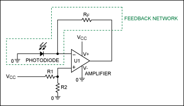
I am designing a trans-impedance amplifier using a TEMD7000X01 photodiode and an AD8551ARZ op-amp. RF is 100 kΩ, CF is 150 pF, and VCC is +3.3 V. The output of the op-amp is connected to an ADC pin of a microcontroller. 

This circuit works as intended when the op-amp is on, but when it is off, because the diode is forward-biased, the voltage at the output is negative, which is an issue for our microcontroller. Adding a small signal diode at the output does help limit the negative voltage, but there is some leakage current which is not ideal. 

I had thought that if the photodiode was reverse-biased instead, it would fix the negative voltage issue when the op-amp is off. This does fix the negative voltage issue when the op-amp is off, but when it is on, the output is stuck at 0. Any advice on how to manipulate the circuit to fix the negative voltage issue?

enter image description here

Source Link

high gain transimpedance amplifier with photodiode not functioning as expected

I am designing a trans-impedance amplifier using a photodiode(TEMD7000X01) and the AD8551ARZ OPAMP. The RF is 100k ohms, CF is 150 pF, and Vcc is +3.3 V. The output of the OPAMP is being fed to an ADC pin of a microcontroller. This circuit works as intended when the OPAMP is on. However, when it is off, because the diode is forward-biased, the voltage at the output is negative, which is an issue for our microcontroller. Adding a small signal diode at the output does help limit the negative voltage, but there is some leakage current which is not ideal. I had thought that if the photodiode was reverse-biased instead, it would fix the negative voltage issue when the OPAMP is off. This does fix the negative voltage issue when the OPAMP is off, but when it is on the output is stuck at 0. Any advice on how to manipulate the circuit to fix the negative voltage issue? thanks!

enter image description here