images inlined
Source Link
Nick Alexeev
  • 38.6k
  • 17
  • 101
  • 240

I will try to answer all of your questions. Maybe this will help you:

First, the generator ratings are given as:

  • \$x_0\$ is the internal zero reactance
  • \$x_2\$ is the internal negative reactance
  • \$ x^"\$ is the internal positive reactance

You can enter these data in the "Fault" window of the "Generator Information for Current Case". Look at the following image:

[enter image description here][1enter image description here
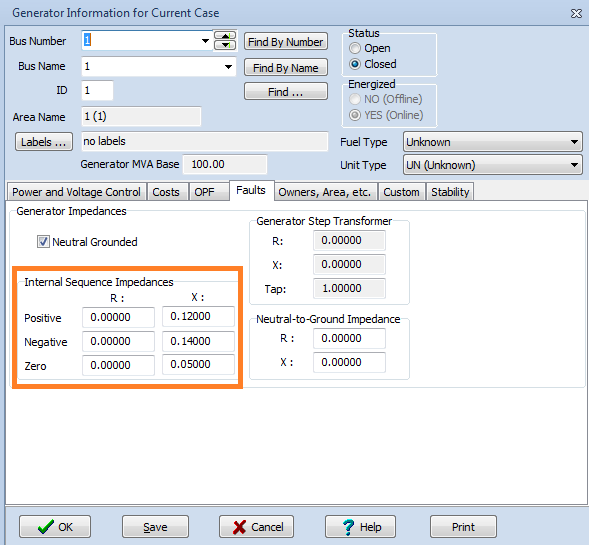
For the second part, you are wrong! Why did you put the data in Ohm/km? You should put it in [per unit][2per unit. Also, you already have the line lengths in km. It should be easy for you to calculate. I will do the first as an example.

The positive/zero sequence impedance can be found by dividing the given values by the the \$ Z_{base} \$, and then multiply it with the line length:

[enter image description here][3enter image description here
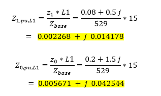
This is just for the first line, you can do the same for the other.

Also, you can enter the positive impedance in the "Parameter" window, and the zero impedance can be entered separately in the "Fault Info" window.

Third, regarding the system blackout. What is your tap ratio in the transformers side? Remember, the typical value for the tap-ratio is between 0.9 and 1.1. Otherwise, the system will not run!

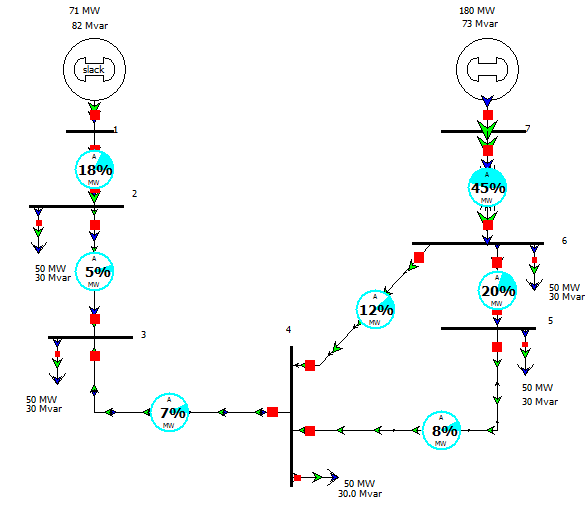
I already simulate your system, and I think it is easy. You can do it by yourself. The system should look like this:

enter image description hereenter image description here

The voltages in all buses should be around 1-pu. I hope this was helpful. You can ask me if you have any question.

Read this file for more information about PowerWorld.

EDIT:

Oh NO!!! I need at least 10 reputation to post images and links!!. Sorry some images will not appear. I will update this post later. Sorry for that.

I will try to answer all of your questions. Maybe this will help you:

First, the generator ratings are given as:

  • \$x_0\$ is the internal zero reactance
  • \$x_2\$ is the internal negative reactance
  • \$ x^"\$ is the internal positive reactance

You can enter these data in the "Fault" window of the "Generator Information for Current Case". Look at the following image:

[enter image description here][1

For the second part, you are wrong! Why did you put the data in Ohm/km? You should put it in [per unit][2. Also, you already have the line lengths in km. It should be easy for you to calculate. I will do the first as an example.

The positive/zero sequence impedance can be found by dividing the given values by the the \$ Z_{base} \$, and then multiply it with the line length:

[enter image description here][3

This is just for the first line, you can do the same for the other.

Also, you can enter the positive impedance in the "Parameter" window, and the zero impedance can be entered separately in the "Fault Info" window.

Third, regarding the system blackout. What is your tap ratio in the transformers side? Remember, the typical value for the tap-ratio is between 0.9 and 1.1. Otherwise, the system will not run!

I already simulate your system, and I think it is easy. You can do it by yourself. The system should look like this:

enter image description here

The voltages in all buses should be around 1-pu. I hope this was helpful. You can ask me if you have any question.

Read this file for more information about PowerWorld.

EDIT:

Oh NO!!! I need at least 10 reputation to post images and links!!. Sorry some images will not appear. I will update this post later. Sorry for that.

I will try to answer all of your questions. Maybe this will help you:

First, the generator ratings are given as:

  • \$x_0\$ is the internal zero reactance
  • \$x_2\$ is the internal negative reactance
  • \$ x^"\$ is the internal positive reactance

You can enter these data in the "Fault" window of the "Generator Information for Current Case". Look at the following image:

enter image description here

For the second part, you are wrong! Why did you put the data in Ohm/km? You should put it in per unit. Also, you already have the line lengths in km. It should be easy for you to calculate. I will do the first as an example.

The positive/zero sequence impedance can be found by dividing the given values by the the \$ Z_{base} \$, and then multiply it with the line length:

enter image description here

This is just for the first line, you can do the same for the other.

Also, you can enter the positive impedance in the "Parameter" window, and the zero impedance can be entered separately in the "Fault Info" window.

Third, regarding the system blackout. What is your tap ratio in the transformers side? Remember, the typical value for the tap-ratio is between 0.9 and 1.1. Otherwise, the system will not run!

I already simulate your system, and I think it is easy. You can do it by yourself. The system should look like this:

enter image description here

The voltages in all buses should be around 1-pu. I hope this was helpful. You can ask me if you have any question.

Read this file for more information about PowerWorld.

Source Link

I will try to answer all of your questions. Maybe this will help you:

First, the generator ratings are given as:

  • \$x_0\$ is the internal zero reactance
  • \$x_2\$ is the internal negative reactance
  • \$ x^"\$ is the internal positive reactance

You can enter these data in the "Fault" window of the "Generator Information for Current Case". Look at the following image:

[enter image description here][1

For the second part, you are wrong! Why did you put the data in Ohm/km? You should put it in [per unit][2. Also, you already have the line lengths in km. It should be easy for you to calculate. I will do the first as an example.

The positive/zero sequence impedance can be found by dividing the given values by the the \$ Z_{base} \$, and then multiply it with the line length:

[enter image description here][3

This is just for the first line, you can do the same for the other.

Also, you can enter the positive impedance in the "Parameter" window, and the zero impedance can be entered separately in the "Fault Info" window.

Third, regarding the system blackout. What is your tap ratio in the transformers side? Remember, the typical value for the tap-ratio is between 0.9 and 1.1. Otherwise, the system will not run!

I already simulate your system, and I think it is easy. You can do it by yourself. The system should look like this:

enter image description here

The voltages in all buses should be around 1-pu. I hope this was helpful. You can ask me if you have any question.

Read this file for more information about PowerWorld.

EDIT:

Oh NO!!! I need at least 10 reputation to post images and links!!. Sorry some images will not appear. I will update this post later. Sorry for that.