added 243 characters in body
Source Link
Andy aka
  • 472.9k
  • 29
  • 382
  • 839

ADDED: THIS IS A GOOD ANSWER TO THE ORIGINAL QUESTION. It assumes that the LED is lit when the GPIO drive pin is high - as originally implied. - RM


while GPIO is 3.3V, I want to drive the LED using 5V source

and

but this FET-based circuit is inverting.

No it isn't, not when driving an LED attached to the drain circuit. You want current through the LED when the GPIO pin is high so, functionally, that's non-inverting.

If source connects to ground and gate is driven by the MCU pin then current flows through the drain-connected-LED when the MCU output pin is high (and activating the MOSFET): -

enter image description here

Image (modified) from here

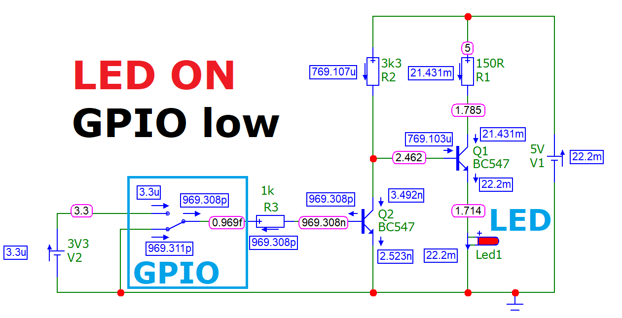
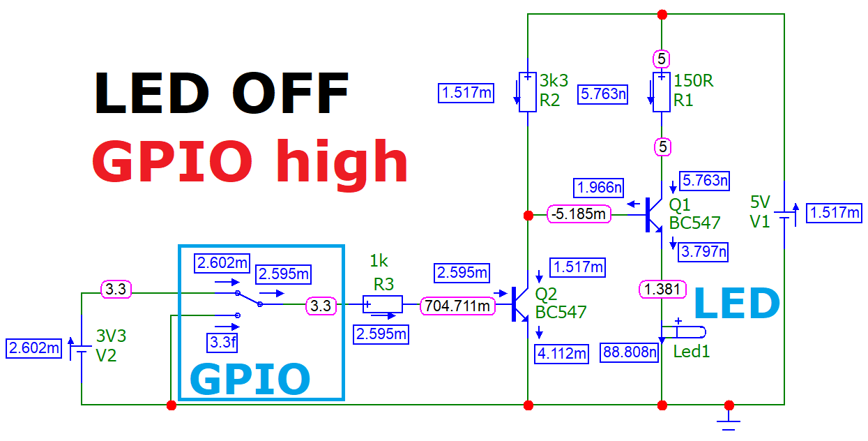
EDIT to invert the logic (using two NPN transistors, CE and CC)

enter image description here

enter image description here

ADDED: THIS IS A GOOD ANSWER TO THE ORIGINAL QUESTION. It assumes that the LED is lit when the GPIO drive pin is high - as originally implied. - RM


while GPIO is 3.3V, I want to drive the LED using 5V source

and

but this FET-based circuit is inverting.

No it isn't, not when driving an LED attached to the drain circuit. You want current through the LED when the GPIO pin is high so, functionally, that's non-inverting.

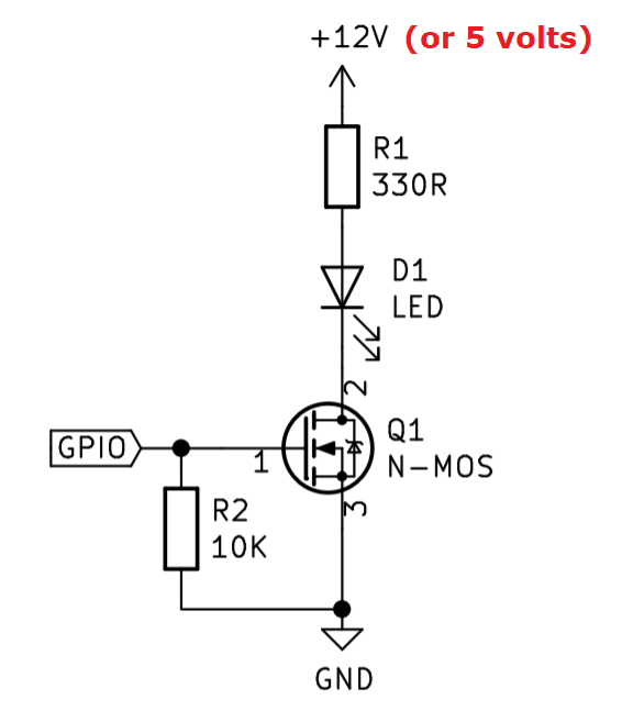
If source connects to ground and gate is driven by the MCU pin then current flows through the drain-connected-LED when the MCU output pin is high (and activating the MOSFET): -

enter image description here

Image (modified) from here

EDIT to invert the logic (using two NPN transistors, CE and CC)
enter image description here

enter image description here

added 189 characters in body
Source Link
Russell McMahon
  • 152.1k
  • 18
  • 218
  • 402

ADDED: THIS IS A GOOD ANSWER TO THE ORIGINAL QUESTION. It assumes that the LED is lit when the GPIO drive pin is high - as originally implied. - RM


while GPIO is 3.3V, I want to drive the LED using 5V source

and

but this FET-based circuit is inverting.

No it isn't, not when driving an LED attached to the drain circuit. You want current through the LED when the GPIO pin is high so, functionally, that's non-inverting.

If source connects to ground and gate is driven by the MCU pin then current flows through the drain-connected-LED when the MCU output pin is high (and activating the MOSFET): -

enter image description here

Image (modified) from here

ADDED: THIS IS A GOOD ANSWER TO THE ORIGINAL QUESTION. It assumes that the LED is lit when the GPIO drive pin is high - as originally implied. - RM


while GPIO is 3.3V, I want to drive the LED using 5V source

and

but this FET-based circuit is inverting.

No it isn't, not when driving an LED attached to the drain circuit. You want current through the LED when the GPIO pin is high so, functionally, that's non-inverting.

If source connects to ground and gate is driven by the MCU pin then current flows through the drain-connected-LED when the MCU output pin is high (and activating the MOSFET): -

enter image description here

Image (modified) from here

added 99 characters in body
Source Link
Andy aka
  • 472.9k
  • 29
  • 382
  • 839

while GPIO is 3.3V, I want to drive the LED using 5V source

and

but this FET-based circuit is inverting.

No it isn't, not when driving an LED attached to the drain circuit. You want current through the LED when the GPIO pin is high so, functionally, that's non-inverting.

If source connects to ground and gate is driven by the MCU pin then current flows through the drain-connected-LED when the MCU output pin is high (and activating the MOSFET): -

enter image description here

Image (modified) from here

while GPIO is 3.3V, I want to drive the LED using 5V source

and

but this FET-based circuit is inverting.

No it isn't, not when driving an LED attached to the drain circuit.

If source connects to ground and gate is driven by the MCU pin then current flows through the drain-connected-LED when the MCU output pin is high (and activating the MOSFET): -

enter image description here

Image (modified) from here

while GPIO is 3.3V, I want to drive the LED using 5V source

and

but this FET-based circuit is inverting.

No it isn't, not when driving an LED attached to the drain circuit. You want current through the LED when the GPIO pin is high so, functionally, that's non-inverting.

If source connects to ground and gate is driven by the MCU pin then current flows through the drain-connected-LED when the MCU output pin is high (and activating the MOSFET): -

enter image description here

Image (modified) from here

Source Link
Andy aka
  • 472.9k
  • 29
  • 382
  • 839
Loading