Added screenshots to support claims; refined phrasing
Source Link
Tim Williams
  • 45.6k
  • 2
  • 32
  • 129

Just to briefly answer part of the question:

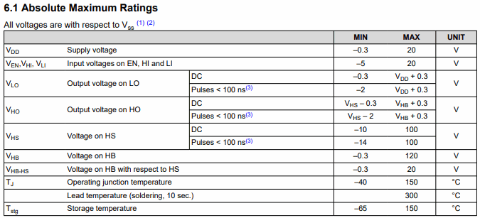
The gate driver does not have a current rating, on any pins actually. If:

enter image description here

If a parameter doesn't appear in the absolute maximum ratings table, don't worry about it. (Well

Well... maybe. This might be Such a principle thatmay occasionally resultsresult in concerned calls to the manufacturer's FAE. But, in that case, whether a bug of documentation or actual chip design, it's at least their fault, not yours. Whether you want to plan for such oversights in a given project, or prefer a more conservative approach, is up to you.)

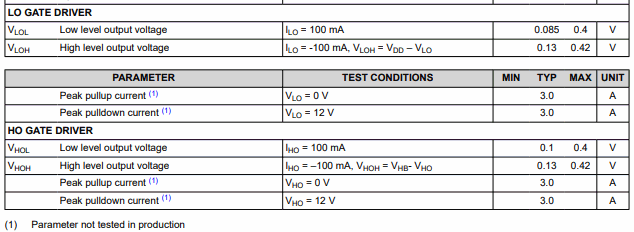
What theThe current rating is,:

enter image description here

is the peak current it's capable of, at all. In this case, only the typical current at that, so, you don't really know how much a random sample will deliver, or under different conditions (in general, it depends on VCC and Tj). It's a characteristic -- what it's capable of, under given conditions; in this case, shorted to the opposite rail.

It'sSo, it's perfectly fine to run a gate circuit with zero external resistance; it'sresistance, at least in the right circumstances.

It's just safer to use onea resistor, partly to have the option of controlling speed, and partly because things can be poorly behaved, particularly when there's much distance between driver and transistor. Without a gate stopper resistor at the transistor, oscillations can occur on switching edges, even at several 100 MHz.

Just to briefly answer part of the question:

The gate driver does not have a current rating, on any pins actually. If a parameter doesn't appear in the absolute maximum ratings table, don't worry about it. (Well... maybe. This might be a principle that occasionally results in concerned calls to the manufacturer's FAE. But, in that case, whether a bug of documentation or actual chip design, it's at least their fault, not yours. Whether you want to plan for such oversights in a given project, or prefer a more conservative approach, is up to you.)

What the current rating is, is the peak current it's capable of, at all. In this case, only the typical current at that, so, you don't really know how much a random sample will deliver, or under different conditions (in general, it depends on VCC and Tj).

It's perfectly fine to run a gate circuit with zero external resistance; it's just safer to use one, partly to have the option of controlling speed, and partly because things can be poorly behaved, particularly when there's much distance between driver and transistor. Without a gate stopper resistor at the transistor, oscillations can occur on switching edges, even at several 100 MHz.
Just to briefly answer part of the question:

The gate driver does not have a current rating, on any pins actually:

enter image description here

If a parameter doesn't appear in the absolute maximum ratings table, don't worry about it.

Well... maybe. Such a principle may occasionally result in concerned calls to the manufacturer's FAE. But, in that case, whether a bug of documentation or actual chip design, it's at least their fault, not yours. Whether you want to plan for such oversights in a given project, or prefer a more conservative approach, is up to you.

The current rating:

enter image description here

is the peak current it's capable of, at all. In this case, only the typical current at that, so, you don't really know how much a random sample will deliver, or under different conditions (in general, it depends on VCC and Tj). It's a characteristic -- what it's capable of, under given conditions; in this case, shorted to the opposite rail.

So, it's perfectly fine to run a gate circuit with zero external resistance, at least in the right circumstances.

It's just safer to use a resistor, partly to have the option of controlling speed, and partly because things can be poorly behaved, particularly when there's much distance between driver and transistor. Without a gate stopper resistor at the transistor, oscillations can occur on switching edges, even at several 100 MHz.

Source Link
Tim Williams
  • 45.6k
  • 2
  • 32
  • 129

Just to briefly answer part of the question:

The gate driver does not have a current rating, on any pins actually. If a parameter doesn't appear in the absolute maximum ratings table, don't worry about it. (Well... maybe. This might be a principle that occasionally results in concerned calls to the manufacturer's FAE. But, in that case, whether a bug of documentation or actual chip design, it's at least their fault, not yours. Whether you want to plan for such oversights in a given project, or prefer a more conservative approach, is up to you.)

What the current rating is, is the peak current it's capable of, at all. In this case, only the typical current at that, so, you don't really know how much a random sample will deliver, or under different conditions (in general, it depends on VCC and Tj).

It's perfectly fine to run a gate circuit with zero external resistance; it's just safer to use one, partly to have the option of controlling speed, and partly because things can be poorly behaved, particularly when there's much distance between driver and transistor. Without a gate stopper resistor at the transistor, oscillations can occur on switching edges, even at several 100 MHz.