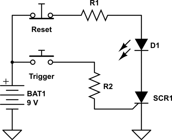
simulate this circuit – Schematic created using CircuitLab
This is a canonical circuit for an intro to silicon controlled rectifiers (SCRs). They are generally three terminal PNPN devices with an anode, cathode, and gate terminal. The device blocks current flow between the anode and cathode until a small current pulse is applied to the gate whereupon it latches into a conductive state and allows current to flow from the anode to the cathode until cathode current falls below some small holding value (Ih).
Use a normally open switch on the gate and a normally closed switch on the anode in series with your LED and resistor. The values of R1 and R2 are dependent on your LED's forward current and SCR's trigger current, respectively. There are plenty of devices out there in a TO92 package with Ih of <5mA so you should be able to find something that works.
If for some reason you are married to a normally-open reset switch, you can place it in parallel across the SCR to shunt current around it and turn it off.
