Typos and grammar improvements.
Source Link
Andrew Morton
  • 2.7k
  • 1
  • 18
  • 28

Decoupling capacitors are important. And they are a cargo cult. We put them in in the hopes that they prevent us from having problems. And they can do the job. You'll just never know if you needed all of them or even if you needed them at all (which is also a bit of a prevention paradox).

Also, measuring noise sometimes boardersborders on black magic. Noise is really hard to measure. It's even harder to measure the results of noise because there could be countless other factors influencing the result.

So, decoupling parts with digital signals is always a good idea. Seeing a result is mostly a question of statistics. Statistics with many measurments over bigger spans of time. 8 measurmentsEight measurements is by far not enoug.enough: I'd suggest to go to at least 1000 and do some statisitcalstatistical analysis if you want to get a usable result.

It's very well possible, that you won't see a difference. But you can be almost 100% sure, that you'll see a difference between a propperproper PCB and a prototyping board!

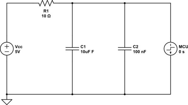
So I'd suggest getting the cap as close to the load as possible. Use 2two caps to be sure (ceramic or foil, maybe 10n or 100n) and a 10u one in parallel. The small one to get the high frequencies, the bigger one to get the slower stuff. Consider putting a small resistor in series to the load:
schematic

simulate this circuit – Schematic created using CircuitLab

This way you get a nice little filter... you can also replace the resistor with an inductor.

Will it be worth it? That's where we enter speculation territory. Maybe? Filtering is often done "just to be sure", "because someone has solved a problem like this in the past" and "because we've always done it that way". Also "because if it doesen'tdoesn't help, it doesn't hurt"...

Decoupling capacitors are important. And they are a cargo cult. We put them in in the hopes that they prevent us from having problems. And they can do the job. You'll just never know if you needed all of them or even if you needed them at all (which is also a bit of a prevention paradox).

Also, measuring noise sometimes boarders on black magic. Noise is really hard to measure. It's even harder to measure the results of noise because there could be countless other factors influencing the result.

So decoupling parts with digital signals is always a good idea. Seeing a result is mostly a question of statistics. Statistics with many measurments over bigger spans of time. 8 measurments is by far not enoug. I'd suggest to go to at least 1000 and do some statisitcal analysis if you want to get a usable result.

It's very well possible, that you won't see a difference. But you can be almost 100% sure, that you'll see a difference between a propper PCB and a prototyping board!

So I'd suggest getting the cap as close to the load as possible. Use 2 caps to be sure (ceramic or foil maybe 10n or 100n) and a 10u one in parallel. The small one to get the high frequencies, the bigger one to get the slower stuff. Consider putting a small resistor in series to the load:

schematic

simulate this circuit – Schematic created using CircuitLab

This way you get a nice little filter... you can also replace the resistor with an inductor.

Will it be worth it? That's where we enter speculation territory. Maybe? Filtering is often done "just to be sure", "because someone has solved a problem like this in the past" and "because we've always done it that way". Also "because if it doesen't help it doesn't hurt"...

Decoupling capacitors are important. And they are a cargo cult. We put them in in the hopes that they prevent us from having problems. And they can do the job. You'll just never know if you needed all of them or even if you needed them at all (which is also a bit of a prevention paradox).

Also, measuring noise sometimes borders on black magic. Noise is really hard to measure. It's even harder to measure the results of noise because there could be countless other factors influencing the result.

So, decoupling parts with digital signals is always a good idea. Seeing a result is mostly a question of statistics. Statistics with many measurments over bigger spans of time. Eight measurements is by far not enough: I'd suggest to go to at least 1000 and do some statistical analysis if you want to get a usable result.

It's very well possible that you won't see a difference. But you can be almost 100% sure that you'll see a difference between a proper PCB and a prototyping board!

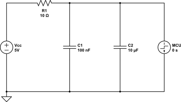
So I'd suggest getting the cap as close to the load as possible. Use two caps to be sure (ceramic or foil, maybe 10n or 100n) and a 10u one in parallel. The small one to get the high frequencies, the bigger one to get the slower stuff. Consider putting a small resistor in series to the load:

schematic

simulate this circuit – Schematic created using CircuitLab

This way you get a nice little filter... you can also replace the resistor with an inductor.

Will it be worth it? That's where we enter speculation territory. Maybe? Filtering is often done "just to be sure", "because someone has solved a problem like this in the past" and "because we've always done it that way". Also "because if it doesn't help, it doesn't hurt"...

Switched the capacitors in the schematic around
Source Link
kruemi
  • 3.8k
  • 18
  • 33

Decoupling capacitors are important. And they are a cargo cult. We put them in in the hopes that they prevent us from having problems. And they can do the job. You'll just never know if you needed all of them or even if you needed them at all (which is also a bit of a prevention paradox).

Also, measuring noise sometimes boarders on black magic. Noise is really hard to measure. It's even harder to measure the results of noise because there could be countless other factors influencing the result.

So decoupling parts with digital signals is always a good idea. Seeing a result is mostly a question of statistics. Statistics with many measurments over bigger spans of time. 8 measurments is by far not enoug. I'd suggest to go to at least 1000 and do some statisitcal analysis if you want to get a usable result.

It's very well possible, that you won't see a difference. But you can be almost 100% sure, that you'll see a difference between a propper PCB and a prototyping board!

So I'd suggest getting the cap as close to the load as possible. Use 2 caps to be sure (ceramic or foil maybe 10n or 100n) and a 10u one in parallel. The small one to get the high frequencies, the bigger one to get the slower stuff. Consider putting a small resistor in series to the load:

schematicschematic

simulate this circuitsimulate this circuit – Schematic created using CircuitLab

This way you get a nice little filter... you can also replace the resistor with an inductor.

Will it be worth it? That's where we enter speculation territory. Maybe? Filtering is often done "just to be sure", "because someone has solved a problem like this in the past" and "because we've always done it that way". Also "because if it doesen't help it doesn't hurt"...

Decoupling capacitors are important. And they are a cargo cult. We put them in in the hopes that they prevent us from having problems. And they can do the job. You'll just never know if you needed all of them or even if you needed them at all (which is also a bit of a prevention paradox).

Also, measuring noise sometimes boarders on black magic. Noise is really hard to measure. It's even harder to measure the results of noise because there could be countless other factors influencing the result.

So decoupling parts with digital signals is always a good idea. Seeing a result is mostly a question of statistics. Statistics with many measurments over bigger spans of time. 8 measurments is by far not enoug. I'd suggest to go to at least 1000 and do some statisitcal analysis if you want to get a usable result.

It's very well possible, that you won't see a difference. But you can be almost 100% sure, that you'll see a difference between a propper PCB and a prototyping board!

So I'd suggest getting the cap as close to the load as possible. Use 2 caps to be sure (ceramic or foil maybe 10n or 100n) and a 10u one in parallel. The small one to get the high frequencies, the bigger one to get the slower stuff. Consider putting a small resistor in series to the load:

schematic

simulate this circuit – Schematic created using CircuitLab

This way you get a nice little filter... you can also replace the resistor with an inductor.

Will it be worth it? That's where we enter speculation territory. Maybe? Filtering is often done "just to be sure", "because someone has solved a problem like this in the past" and "because we've always done it that way". Also "because if it doesen't help it doesn't hurt"...

replaced "deblocking" by "decoupling"
Source Link
kruemi
  • 3.8k
  • 18
  • 33

DeblockingDecoupling capacitors are important. And they are a cargo cult. We put them in in the hopes that they prevent us from having problems. And they can do the job. You'll just never know if you needed all of them or even if you needed them at all (which is also a bit of a prevention paradox).

Also, measuring noise sometimes boarders on black magic. Noise is really hard to measure. It's even harder to measure the results of noise because there could be countless other factors influencing the result.

So deblockingdecoupling parts with digital signals is always a good idea. Seeing a result is mostly a question of statistics. Statistics with many measurments over bigger spans of time. 8 measurments is by far not enoug. I'd suggest to go to at least 1000 and do some statisitcal analysis if you want to get a usable result.

It's very well possible, that you won't see a difference. But you can be almost 100% sure, that you'll see a difference between a propper PCB and a prototyping board!

So I'd suggest getting the cap as close to the load as possible. Use 2 caps to be sure (ceramic or foil maybe 10n or 100n) and a 10u one in parallel. The small one to get the high frequencies, the bigger one to get the slower stuff. Consider putting a small resistor in series to the load:

schematic

simulate this circuit – Schematic created using CircuitLab

This way you get a nice little filter... you can also replace the resistor with an inductor.

Will it be worth it? That's where we enter speculation territory. Maybe? Filtering is often done "just to be sure", "because someone has solved a problem like this in the past" and "because we've always done it that way". Also "because if it doesen't help it doesn't hurt"...

Deblocking capacitors are important. And they are a cargo cult. We put them in in the hopes that they prevent us from having problems. And they can do the job. You'll just never know if you needed all of them or even if you needed them at all (which is also a bit of a prevention paradox).

Also, measuring noise sometimes boarders on black magic. Noise is really hard to measure. It's even harder to measure the results of noise because there could be countless other factors influencing the result.

So deblocking parts with digital signals is always a good idea. Seeing a result is mostly a question of statistics. Statistics with many measurments over bigger spans of time. 8 measurments is by far not enoug. I'd suggest to go to at least 1000 and do some statisitcal analysis if you want to get a usable result.

It's very well possible, that you won't see a difference. But you can be almost 100% sure, that you'll see a difference between a propper PCB and a prototyping board!

So I'd suggest getting the cap as close to the load as possible. Use 2 caps to be sure (ceramic or foil maybe 10n or 100n) and a 10u one in parallel. The small one to get the high frequencies, the bigger one to get the slower stuff. Consider putting a small resistor in series to the load:

schematic

simulate this circuit – Schematic created using CircuitLab

This way you get a nice little filter... you can also replace the resistor with an inductor.

Will it be worth it? That's where we enter speculation territory. Maybe? Filtering is often done "just to be sure", "because someone has solved a problem like this in the past" and "because we've always done it that way". Also "because if it doesen't help it doesn't hurt"...

Decoupling capacitors are important. And they are a cargo cult. We put them in in the hopes that they prevent us from having problems. And they can do the job. You'll just never know if you needed all of them or even if you needed them at all (which is also a bit of a prevention paradox).

Also, measuring noise sometimes boarders on black magic. Noise is really hard to measure. It's even harder to measure the results of noise because there could be countless other factors influencing the result.

So decoupling parts with digital signals is always a good idea. Seeing a result is mostly a question of statistics. Statistics with many measurments over bigger spans of time. 8 measurments is by far not enoug. I'd suggest to go to at least 1000 and do some statisitcal analysis if you want to get a usable result.

It's very well possible, that you won't see a difference. But you can be almost 100% sure, that you'll see a difference between a propper PCB and a prototyping board!

So I'd suggest getting the cap as close to the load as possible. Use 2 caps to be sure (ceramic or foil maybe 10n or 100n) and a 10u one in parallel. The small one to get the high frequencies, the bigger one to get the slower stuff. Consider putting a small resistor in series to the load:

schematic

simulate this circuit – Schematic created using CircuitLab

This way you get a nice little filter... you can also replace the resistor with an inductor.

Will it be worth it? That's where we enter speculation territory. Maybe? Filtering is often done "just to be sure", "because someone has solved a problem like this in the past" and "because we've always done it that way". Also "because if it doesen't help it doesn't hurt"...

Source Link
kruemi
  • 3.8k
  • 18
  • 33
Loading