edits Have a nice day!
Source Link
Voltage Spike
  • 88.8k
  • 49
  • 90
  • 234

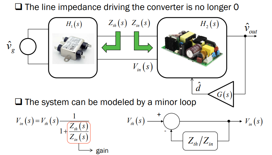
It is said that the output impedance of an EMI filter needs to be largely lower than the input impedance of a converter in order to have no stability issues.

From this document written by Christophe Basso, there is this slide:

enter image description here

What I understand is that Zth is equal to the output impedance of the filter and Zin is equal to the input impedance of the converter.

As Zin correspond to the input impedance of the filter, by nature of a converter, the input impedance has a phase equal to -180°. It means that the input impedance is negative. So when the magnitude of \$Z_{in}\$ and \$Z_{th}\$ is equal, then the above transfer function goes to infinity, and it means that the transfer function is unstable and so \$V_{in}\$ is oscillating. (At this point from my side it does not mean that the output voltage of the converter is unstable? The input voltage could be oscillating without making the output voltage oscillating. There is something that I do not understand.)

Suppose I have a converter with a magnitude input impedance equal to 1 Ω at low frequencies. At low frequency, the output voltage is almost perfectly regulated and the phase of the input impedance is equal to -180°. Then I place an LC filter with a frequency resonance at high frequency. So the output impedance of the LC filter is almost 0 at low frequencies. (Particularly if I use a low inductor).

Then suppose I have a battery with an output impedance equal to 1 Ω at low frequencies. So it makes the transfer function goes to infinity. The magnitude of \$Z_{th}\$ and \$Z_{in}\$ are equal and the phase of \$Z_{in}\$ is negative.

I tried to simulate it under SIMPLIS, but I was not able to get results really convincing me.

Also, as it is necessary to have a certain margin between the output impedance and the input impedance, I wanted to see what would be the consequences of reducing the margin between the output impedance of the battery and the input impedance of the converter, but I was not able to see anything.

So my question is: Does the output impedance of a battery can have an effect on the stability of a converter if the input impedance of the converter is in the vicinity of the output impedance of the battery? I mean on SIMPLIS I am able to see the effect of an LC filter if it not correctly attenuated, and I see the effect on the stability margin. But an LC filter is largely different than just a DC resistor as output impedance like it could be on a battery. In the case of a resistor there is no modification of the phase contrary to an LC filter. 050460

It is said that the output impedance of an EMI filter needs to be largely lower than the input impedance of a converter in order to have no stability issues.

From this document written by Christophe Basso, there is this slide:

enter image description here

What I understand is that Zth is equal to the output impedance of the filter and Zin is equal to the input impedance of the converter.

As Zin correspond to the input impedance of the filter, by nature of a converter, the input impedance has a phase equal to -180°. It means that the input impedance is negative. So when the magnitude of \$Z_{in}\$ and \$Z_{th}\$ is equal, then the above transfer function goes to infinity, and it means that the transfer function is unstable and so \$V_{in}\$ is oscillating. (At this point from my side it does not mean that the output voltage of the converter is unstable? The input voltage could be oscillating without making the output voltage oscillating. There is something that I do not understand.)

Suppose I have a converter with a magnitude input impedance equal to 1 Ω at low frequencies. At low frequency, the output voltage is almost perfectly regulated and the phase of the input impedance is equal to -180°. Then I place an LC filter with a frequency resonance at high frequency. So the output impedance of the LC filter is almost 0 at low frequencies. (Particularly if I use a low inductor).

Then suppose I have a battery with an output impedance equal to 1 Ω at low frequencies. So it makes the transfer function goes to infinity. The magnitude of \$Z_{th}\$ and \$Z_{in}\$ are equal and the phase of \$Z_{in}\$ is negative.

I tried to simulate it under SIMPLIS, but I was not able to get results really convincing me.

Also, as it is necessary to have a certain margin between the output impedance and the input impedance, I wanted to see what would be the consequences of reducing the margin between the output impedance of the battery and the input impedance of the converter, but I was not able to see anything.

So my question is: Does the output impedance of a battery can have an effect on the stability of a converter if the input impedance of the converter is in the vicinity of the output impedance of the battery? I mean on SIMPLIS I am able to see the effect of an LC filter if it not correctly attenuated, and I see the effect on the stability margin. But an LC filter is largely different than just a DC resistor as output impedance like it could be on a battery. In the case of a resistor there is no modification of the phase contrary to an LC filter.

Have a nice day! 050460

It is said that the output impedance of an EMI filter needs to be largely lower than the input impedance of a converter in order to have no stability issues.

From this document written by Christophe Basso, there is this slide:

enter image description here

What I understand is that Zth is equal to the output impedance of the filter and Zin is equal to the input impedance of the converter.

As Zin correspond to the input impedance of the filter, by nature of a converter, the input impedance has a phase equal to -180°. It means that the input impedance is negative. So when the magnitude of \$Z_{in}\$ and \$Z_{th}\$ is equal, then the above transfer function goes to infinity, and it means that the transfer function is unstable and so \$V_{in}\$ is oscillating. (At this point from my side it does not mean that the output voltage of the converter is unstable? The input voltage could be oscillating without making the output voltage oscillating. There is something that I do not understand.)

Suppose I have a converter with a magnitude input impedance equal to 1 Ω at low frequencies. At low frequency, the output voltage is almost perfectly regulated and the phase of the input impedance is equal to -180°. Then I place an LC filter with a frequency resonance at high frequency. So the output impedance of the LC filter is almost 0 at low frequencies. (Particularly if I use a low inductor).

Then suppose I have a battery with an output impedance equal to 1 Ω at low frequencies. So it makes the transfer function goes to infinity. The magnitude of \$Z_{th}\$ and \$Z_{in}\$ are equal and the phase of \$Z_{in}\$ is negative.

I tried to simulate it under SIMPLIS, but I was not able to get results really convincing me.

Also, as it is necessary to have a certain margin between the output impedance and the input impedance, I wanted to see what would be the consequences of reducing the margin between the output impedance of the battery and the input impedance of the converter, but I was not able to see anything.

So my question is: Does the output impedance of a battery can have an effect on the stability of a converter if the input impedance of the converter is in the vicinity of the output impedance of the battery? I mean on SIMPLIS I am able to see the effect of an LC filter if it not correctly attenuated, and I see the effect on the stability margin. But an LC filter is largely different than just a DC resistor as output impedance like it could be on a battery. In the case of a resistor there is no modification of the phase contrary to an LC filter.

Have a nice day!

It is said that the output impedance of an EMI filter needs to be largely lower than the input impedance of a converter in order to have no stability issues.

From this document written by Christophe Basso, there is this slide:

enter image description here

What I understand is that Zth is equal to the output impedance of the filter and Zin is equal to the input impedance of the converter.

As Zin correspond to the input impedance of the filter, by nature of a converter, the input impedance has a phase equal to -180°. It means that the input impedance is negative. So when the magnitude of \$Z_{in}\$ and \$Z_{th}\$ is equal, then the above transfer function goes to infinity, and it means that the transfer function is unstable and so \$V_{in}\$ is oscillating. (At this point from my side it does not mean that the output voltage of the converter is unstable? The input voltage could be oscillating without making the output voltage oscillating. There is something that I do not understand.)

Suppose I have a converter with a magnitude input impedance equal to 1 Ω at low frequencies. At low frequency, the output voltage is almost perfectly regulated and the phase of the input impedance is equal to -180°. Then I place an LC filter with a frequency resonance at high frequency. So the output impedance of the LC filter is almost 0 at low frequencies. (Particularly if I use a low inductor).

Then suppose I have a battery with an output impedance equal to 1 Ω at low frequencies. So it makes the transfer function goes to infinity. The magnitude of \$Z_{th}\$ and \$Z_{in}\$ are equal and the phase of \$Z_{in}\$ is negative.

I tried to simulate it under SIMPLIS, but I was not able to get results really convincing me.

Also, as it is necessary to have a certain margin between the output impedance and the input impedance, I wanted to see what would be the consequences of reducing the margin between the output impedance of the battery and the input impedance of the converter, but I was not able to see anything.

So my question is: Does the output impedance of a battery can have an effect on the stability of a converter if the input impedance of the converter is in the vicinity of the output impedance of the battery? I mean on SIMPLIS I am able to see the effect of an LC filter if it not correctly attenuated, and I see the effect on the stability margin. But an LC filter is largely different than just a DC resistor as output impedance like it could be on a battery. In the case of a resistor there is no modification of the phase contrary to an LC filter. 050460

Became Hot Network Question

It is said that the output impedance of an EMI filter needs to be largely lower than the input impedance of a converter in order to have no stability issues.

From this document written by Christophe Basso, there is this slide:

enter image description here

What I understand is that Zth is equal to the output impedance of the filter and Zin is equal to the input impedance of the converter.

As Zin correspond to the input impedance of the filter, by nature of a converter, the input impedance has a phase equal to -180°. It means that the input impedance is negative. So when the magnitude of Zin\$Z_{in}\$ and Zth\$Z_{th}\$ is equal, then the above transfer function goes to infinity, and it means that the transfer function is unstable and so Vin\$V_{in}\$ is oscillating. (At this point from my side it does not meansmean that the output voltage of the converter is unstable? The input voltage could be oscillating without making the output voltage oscillating. There is something that I do not understand.)

Suppose I have a converter with a magnitude input impedance equal to 1 Ω at low frequencies. At low frequency, the output voltage is almost perfectly regulated and the phase of the input impedance is equal to -180°. Then I place an LC filter with a frequency resonance at high frequency. So the output impendanceimpedance of the LC filter is almost 0 at low frequencies. (Particularly if I use a low inductor).

Then suppose I have a battery with an output impedance equal to 1 Ω at low frequencies. So it makes the transfer function goes to infinity. The magnitude of Zth\$Z_{th}\$ and Zin\$Z_{in}\$ are equal and the phase of Zin\$Z_{in}\$ is negative.

I tried to simulate it under SIMPLIS, but I was not able to get results really convincing me.

Also, as it is necessary to have a certain margin between the output impedance and the input impedance, I wanted to see what would be the consequences byof reducing the margin between the output impedance of the battery and the input impedance of the converter, but I was not able to see anything.

So my question is: Does the output impedance of a battery can have an effect on the stability of a converter if the input impedance of the converter is in the vicinity of the output impedance of the battery? I mean on SIMPLIS I am able to see the effect of an LC filter if it not correctly attenuated, and I see the effect on the stability margin. But an LC filter is largely different than just a DC resistor as output impedance like it could be on a battery. In the case of a resistor there is no modification of the phase contrary to an LC filter.

Have a nice day!

It is said that the output impedance of an EMI filter needs to be largely lower than the input impedance of a converter in order to have no stability issues.

From this document written by Christophe Basso, there is this slide:

enter image description here

What I understand is that Zth is equal to the output impedance of the filter and Zin is equal to the input impedance of the converter.

As Zin correspond to the input impedance of the filter, by nature of a converter, the input impedance has a phase equal to -180°. It means that the input impedance is negative. So when the magnitude of Zin and Zth is equal, then the above transfer function goes to infinity and it means that the transfer function is unstable and so Vin is oscillating. (At this point from my side it does not means that the output voltage of the converter is unstable? The input voltage could be oscillating without making the output voltage oscillating. There is something that I do not understand.)

Suppose I have a converter with a magnitude input impedance equal to 1 Ω at low frequencies. At low frequency, the output voltage is almost perfectly regulated and the phase of the input impedance is equal to -180°. Then I place an LC filter with a frequency resonance at high frequency. So the output impendance of the LC filter is almost 0 at low frequencies. (Particularly if I use a low inductor).

Then suppose I have a battery with an output impedance equal to 1 Ω at low frequencies. So it makes the transfer function goes to infinity. The magnitude of Zth and Zin are equal and the phase of Zin is negative.

I tried to simulate it under SIMPLIS, but I was not able to get results really convincing me.

Also as it is necessary to have a certain margin between the output impedance and the input impedance, I wanted to see what would be the consequences by reducing the margin between the output impedance of the battery and the input impedance of the converter but I was not able to see anything.

So my question is: Does the output impedance of a battery can have an effect on the stability of a converter if the input impedance of the converter is in the vicinity of the output impedance of the battery? I mean on SIMPLIS I am able to see the effect of an LC filter if it not correctly attenuated and I see the effect on the stability margin. But an LC filter is largely different than just a DC resistor as output impedance like it could be on a battery. In the case of a resistor there is no modification of the phase contrary to an LC filter.

Have a nice day!

It is said that the output impedance of an EMI filter needs to be largely lower than the input impedance of a converter in order to have no stability issues.

From this document written by Christophe Basso, there is this slide:

enter image description here

What I understand is that Zth is equal to the output impedance of the filter and Zin is equal to the input impedance of the converter.

As Zin correspond to the input impedance of the filter, by nature of a converter, the input impedance has a phase equal to -180°. It means that the input impedance is negative. So when the magnitude of \$Z_{in}\$ and \$Z_{th}\$ is equal, then the above transfer function goes to infinity, and it means that the transfer function is unstable and so \$V_{in}\$ is oscillating. (At this point from my side it does not mean that the output voltage of the converter is unstable? The input voltage could be oscillating without making the output voltage oscillating. There is something that I do not understand.)

Suppose I have a converter with a magnitude input impedance equal to 1 Ω at low frequencies. At low frequency, the output voltage is almost perfectly regulated and the phase of the input impedance is equal to -180°. Then I place an LC filter with a frequency resonance at high frequency. So the output impedance of the LC filter is almost 0 at low frequencies. (Particularly if I use a low inductor).

Then suppose I have a battery with an output impedance equal to 1 Ω at low frequencies. So it makes the transfer function goes to infinity. The magnitude of \$Z_{th}\$ and \$Z_{in}\$ are equal and the phase of \$Z_{in}\$ is negative.

I tried to simulate it under SIMPLIS, but I was not able to get results really convincing me.

Also, as it is necessary to have a certain margin between the output impedance and the input impedance, I wanted to see what would be the consequences of reducing the margin between the output impedance of the battery and the input impedance of the converter, but I was not able to see anything.

So my question is: Does the output impedance of a battery can have an effect on the stability of a converter if the input impedance of the converter is in the vicinity of the output impedance of the battery? I mean on SIMPLIS I am able to see the effect of an LC filter if it not correctly attenuated, and I see the effect on the stability margin. But an LC filter is largely different than just a DC resistor as output impedance like it could be on a battery. In the case of a resistor there is no modification of the phase contrary to an LC filter.

Have a nice day!

No space before comma nor question mark in English
Source Link
winny
  • 16.8k
  • 6
  • 50
  • 71
Loading
Source Link
Jess
  • 2.6k
  • 3
  • 27
  • 73
Loading