added 34 characters in body
Source Link
Neil_UK
  • 173.7k
  • 3
  • 194
  • 433

You need a full wave rectifier.

Unfortunately a 'typical' coil with 'typical' magnet strengths and speeds will produce a fairly low voltage, so ordinary rectifier diodes will eat most of your generated voltage.
schematic

simulate this circuit – Schematic created using CircuitLab

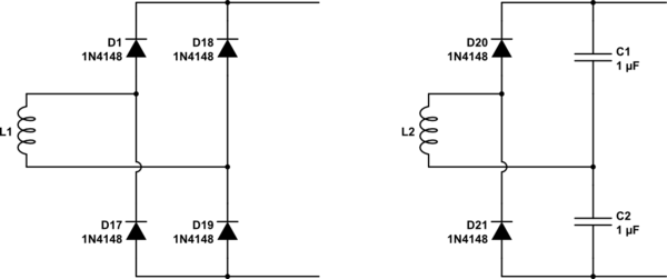
The diagram on the left shows the standard full bridge rectifier. With the silicon diodes shown, you'll need at least 2 diodes drop of somewhere around 1.2 V generated before significant current is available at the outputs. With schottky diodes, the excess voltage needed drops to around 0.6 V or so. 1

The diagram on the right is a 'voltage doubler' circuit, that only requires one diode drop extra from the generating coil before it provides useful output. With schottky diodes only 0.3 V is needed. Size the capacitors according to your load, there's only 1 uF shown there as it's the default, you may want capacitors in the 1000's of uF.

To scrape a few extra 10's of mV, note that power diodes will generally have a lower voltage drop at any given current than small signal diodes.

It is possible to get lower voltage drop, approaching zero, in the rectifying devices if you use actively controlled FETs, but it gets complicated, and usually needs an external power source to get it going, especially if the motivationpurpose is to handle very low input voltages.

In a DC permanent magnet generator, the 'rectification' is done by switches, cleverly sequenced by being mounted on the same shaft as the coils, in an arrangement called a commutator

1 Diodes actually conduct at any voltage, but due to the exponential relationship between voltage and current, you don't get 'useful' levels of current, let's say a decent fractionin the order of a mA, before you get to the suggested diode voltages. You can read lower voltage drops if your only load is the voltage input of a DMM.

You need a full wave rectifier.

Unfortunately a 'typical' coil with 'typical' magnet strengths and speeds will produce a fairly low voltage, so ordinary rectifier diodes will eat most of your generated voltage.

schematic

simulate this circuit – Schematic created using CircuitLab

The diagram on the left shows the standard full bridge rectifier. With the silicon diodes shown, you'll need at least 2 diodes drop of somewhere around 1.2 V generated before significant current is available at the outputs. With schottky diodes, the excess voltage needed drops to around 0.6 V or so. 1

The diagram on the right is a 'voltage doubler' circuit, that only requires one diode drop extra from the generating coil before it provides useful output. With schottky diodes only 0.3 V is needed. Size the capacitors according to your load, there's only 1 uF shown there as it's the default, you may want capacitors in the 1000's of uF.

To scrape a few extra 10's of mV, note that power diodes will generally have a lower voltage drop at any given current than small signal diodes.

It is possible to get lower voltage drop, approaching zero, in the rectifying devices if you use actively controlled FETs, but it gets complicated, and usually needs an external power source to get it going, especially if the motivation is to handle very low voltages.

In a DC permanent magnet generator, the 'rectification' is done by switches, cleverly sequenced by being mounted on the same shaft as the coils, in an arrangement called a commutator

1 Diodes actually conduct at any voltage, but due to the exponential relationship between voltage and current, you don't get 'useful' levels of current, let's say a decent fraction of a mA, before you get to the suggested diode voltages.

You need a full wave rectifier.

Unfortunately a 'typical' coil with 'typical' magnet strengths and speeds will produce a fairly low voltage, so ordinary rectifier diodes will eat most of your generated voltage.

schematic

simulate this circuit – Schematic created using CircuitLab

The diagram on the left shows the standard full bridge rectifier. With the silicon diodes shown, you'll need at least 2 diodes drop of somewhere around 1.2 V generated before significant current is available at the outputs. With schottky diodes, the excess voltage needed drops to around 0.6 V or so. 1

The diagram on the right is a 'voltage doubler' circuit, that only requires one diode drop extra from the generating coil before it provides useful output. With schottky diodes only 0.3 V is needed. Size the capacitors according to your load, there's only 1 uF shown there as it's the default, you may want capacitors in the 1000's of uF.

To scrape a few extra 10's of mV, note that power diodes will generally have a lower voltage drop at any given current than small signal diodes.

It is possible to get lower voltage drop, approaching zero, if you use actively controlled FETs, but it gets complicated, and needs an external power source to get it going if the purpose is to handle very low input voltages.

In a DC permanent magnet generator, the 'rectification' is done by switches, cleverly sequenced by being mounted on the same shaft as the coils, in an arrangement called a commutator

1 Diodes actually conduct at any voltage, but due to the exponential relationship between voltage and current, you don't get 'useful' levels of current, let's say in the order of a mA, before you get to the suggested diode voltages. You can read lower voltage drops if your only load is the voltage input of a DMM.

added 691 characters in body
Source Link
Neil_UK
  • 173.7k
  • 3
  • 194
  • 433

All youYou need is a full wave rectifier.

Unfortunately a 'typical' coil with 'typical' magnet strengths and speeds will produce a fairly low voltage, so ordinary rectifier diodes will eat most of your generated voltage.

schematic

simulate this circuit – Schematic created using CircuitLab

The diagram on the left shows the standard full bridge rectifier. With the silicon diodes shown, you'll need at least 2 diodes drop of somewhere around 1.2 V generated before significant current is available at the outputs. With schottky diodes, the excess voltage needed drops to around 0.6 V or so. 1

The diagram on the right is a 'voltage doubler' circuit, that only requires one diode drop extra from the generating coil before it provides useful output. With schottky diodes only 0.3 V is needed. Size the capacitors according to your load, there's only 1 uF shown there as it's the default, you may want capacitors in the 1000's of uF. 

To scrape a few extra 10's of mV, note that power diodes will generally have a lower voltage drop at any given current than small signal diodes.

It is possible to get lower voltage drop, approaching zero, in the rectifying devices if you use actively controlled FETsactively controlled FETs, but it gets complicated, and usually needs an external power source to get it going. I'll leave you, especially if the motivation is to find thosehandle very low voltages.

In a DC permanent magnet generator, orthe 'rectification' is done by switches, cleverly sequenced by being mounted on the same shaft as the coils, in an arrangement called a commutator

1 Diodes actually conduct at any voltage, but due to othersthe exponential relationship between voltage and current, you don't get 'useful' levels of current, let's say a decent fraction of a mA, before you get to provide an answer covering themthe suggested diode voltages.

All you need is a full wave rectifier.

Unfortunately a 'typical' coil with 'typical' magnet strengths and speeds will produce a fairly low voltage, so ordinary rectifier diodes will eat most of your generated voltage.

schematic

simulate this circuit – Schematic created using CircuitLab

The diagram on the left shows the standard full bridge rectifier. With the silicon diodes shown, you'll need at least 2 diodes drop of somewhere around 1.2 V generated before significant current is available at the outputs. With schottky diodes, the excess voltage needed drops to around 0.6 V or so.

The diagram on the right is a 'voltage doubler' circuit, that only requires one diode drop extra from the generating coil before it provides useful output. With schottky diodes only 0.3 V is needed. To scrape a few extra mV, note that power diodes will generally have a lower voltage drop at any given current than small signal diodes.

It is possible to get lower voltage drop, approaching zero, in the rectifying devices if you use actively controlled FETs, but it gets complicated, and usually needs an external power source to get it going. I'll leave you to find those, or to others to provide an answer covering them.

You need a full wave rectifier.

Unfortunately a 'typical' coil with 'typical' magnet strengths and speeds will produce a fairly low voltage, so ordinary rectifier diodes will eat most of your generated voltage.

schematic

simulate this circuit – Schematic created using CircuitLab

The diagram on the left shows the standard full bridge rectifier. With the silicon diodes shown, you'll need at least 2 diodes drop of somewhere around 1.2 V generated before significant current is available at the outputs. With schottky diodes, the excess voltage needed drops to around 0.6 V or so. 1

The diagram on the right is a 'voltage doubler' circuit, that only requires one diode drop extra from the generating coil before it provides useful output. With schottky diodes only 0.3 V is needed. Size the capacitors according to your load, there's only 1 uF shown there as it's the default, you may want capacitors in the 1000's of uF. 

To scrape a few extra 10's of mV, note that power diodes will generally have a lower voltage drop at any given current than small signal diodes.

It is possible to get lower voltage drop, approaching zero, in the rectifying devices if you use actively controlled FETs, but it gets complicated, and usually needs an external power source to get it going, especially if the motivation is to handle very low voltages.

In a DC permanent magnet generator, the 'rectification' is done by switches, cleverly sequenced by being mounted on the same shaft as the coils, in an arrangement called a commutator

1 Diodes actually conduct at any voltage, but due to the exponential relationship between voltage and current, you don't get 'useful' levels of current, let's say a decent fraction of a mA, before you get to the suggested diode voltages.

Source Link
Neil_UK
  • 173.7k
  • 3
  • 194
  • 433

All you need is a full wave rectifier.

Unfortunately a 'typical' coil with 'typical' magnet strengths and speeds will produce a fairly low voltage, so ordinary rectifier diodes will eat most of your generated voltage.

schematic

simulate this circuit – Schematic created using CircuitLab

The diagram on the left shows the standard full bridge rectifier. With the silicon diodes shown, you'll need at least 2 diodes drop of somewhere around 1.2 V generated before significant current is available at the outputs. With schottky diodes, the excess voltage needed drops to around 0.6 V or so.

The diagram on the right is a 'voltage doubler' circuit, that only requires one diode drop extra from the generating coil before it provides useful output. With schottky diodes only 0.3 V is needed. To scrape a few extra mV, note that power diodes will generally have a lower voltage drop at any given current than small signal diodes.

It is possible to get lower voltage drop, approaching zero, in the rectifying devices if you use actively controlled FETs, but it gets complicated, and usually needs an external power source to get it going. I'll leave you to find those, or to others to provide an answer covering them.