Note about D2 leakage (thanks Neil_UK!)
Source Link
jpa
  • 9.7k
  • 22
  • 42

The other answers work if you don't mind the high voltage drop in the 1 Mohm resistor. But if your device sometimes draws higher current before going to sleep mode, you can use a transimpedance amplifier to provide constant supply voltage to the load.
schematic

simulate this circuit – Schematic created using CircuitLab

The opamps should be supplied with a voltage higher than the desired output voltage, for example +15V. OA1 should be selected to have high enough max output current to meet the demands of the load.

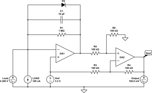
OA1 is connected as a transimpedance amplifier, and its output will be VOA1 = VREF + R1 × ILOAD. C1 acts as a low pass filter to improve stability and reduce noise. 

Zener D2 is optional, but it allows the load voltage to stay in regulation even if the measurement range is exceeded. Pay attention to its leakage current, which would affect accuracy.

OA2 subtracts VREF from VOA1 and provides 1 mV per nA output.

The other answers work if you don't mind the high voltage drop in the 1 Mohm resistor. But if your device sometimes draws higher current before going to sleep mode, you can use a transimpedance amplifier to provide constant supply voltage to the load.

schematic

simulate this circuit – Schematic created using CircuitLab

The opamps should be supplied with a voltage higher than the desired output voltage, for example +15V. OA1 should be selected to have high enough max output current to meet the demands of the load.

OA1 is connected as a transimpedance amplifier, and its output will be VOA1 = VREF + R1 × ILOAD. C1 acts as a low pass filter to improve stability and reduce noise. Zener D2 is optional, but it allows the load voltage to stay in regulation even if the measurement range is exceeded.

OA2 subtracts VREF from VOA1 and provides 1 mV per nA output.

The other answers work if you don't mind the high voltage drop in the 1 Mohm resistor. But if your device sometimes draws higher current before going to sleep mode, you can use a transimpedance amplifier to provide constant supply voltage to the load.

schematic

simulate this circuit – Schematic created using CircuitLab

The opamps should be supplied with a voltage higher than the desired output voltage, for example +15V. OA1 should be selected to have high enough max output current to meet the demands of the load.

OA1 is connected as a transimpedance amplifier, and its output will be VOA1 = VREF + R1 × ILOAD. C1 acts as a low pass filter to improve stability and reduce noise. 

Zener D2 is optional, but it allows the load voltage to stay in regulation even if the measurement range is exceeded. Pay attention to its leakage current, which would affect accuracy.

OA2 subtracts VREF from VOA1 and provides 1 mV per nA output.

Source Link
jpa
  • 9.7k
  • 22
  • 42

The other answers work if you don't mind the high voltage drop in the 1 Mohm resistor. But if your device sometimes draws higher current before going to sleep mode, you can use a transimpedance amplifier to provide constant supply voltage to the load.

schematic

simulate this circuit – Schematic created using CircuitLab

The opamps should be supplied with a voltage higher than the desired output voltage, for example +15V. OA1 should be selected to have high enough max output current to meet the demands of the load.

OA1 is connected as a transimpedance amplifier, and its output will be VOA1 = VREF + R1 × ILOAD. C1 acts as a low pass filter to improve stability and reduce noise. Zener D2 is optional, but it allows the load voltage to stay in regulation even if the measurement range is exceeded.

OA2 subtracts VREF from VOA1 and provides 1 mV per nA output.