1
\$\begingroup\$

The product I currently design (a fork sensor) has a metal chassis which is not connected to earth ground. Examining the product of a competitor, I see there is a large SMD capacitor between it's chassis and ground. Thanks to some folks here, I was able to understand its purpose: to prevent RF noise from coupling to sensitive analog parts of the device. (Also includes capacitor photo)

However, these devices are subject to a dielectric test in certification, which applies 500VAC RMS voltage between chassis and exposed pins. I am having a real hard time finding an SMD capacitor with 500VAC rating.

My plan is to place an MLCC type capacitor with 1000V withstand voltage. 500VAC test signal will have about 700V peak voltage which my capacitor should be able to handle. However, this time the capacitance value is a problem. The sample I have has about 60nF of capacitance. Doing the math, about 4.7W is wasted on the capacitor. (I don't know how the sample does it, or if it conforms to standard, I couldn't find it in their website)

(Edit: I recently learned that capacitor power calculation is not done that way.)

Then I had an idea: MLCCs tend to have a capacitance drop in high DC voltages, which means lower currents will flow! This is the exact behavior I want: bypass low amplitude noise, and block high amplitude test signal.

How do MLCCs behave with low frequency/high voltage signals? Does this capacitance drop also show itself in 50 Hz?

I would also glad if you can suggest me any capacitor to use in this scenario. I found these AC Safety Capacitors as an alternative. However I don't know how long will these last with 500VAC. It is above their rating, however below their withstanding voltage.

If none of these work, I will just plug in a capacitor very low capacitance and pray it filters enough noise in the application.

Edit: as mentioned above, I learned that the power consumption isn't a real problem, which probably solves the issue. Still, I would like to know the answer to the question, for the sake of curiosity.

\$\endgroup\$
0

1 Answer 1

1
\$\begingroup\$

MLCCs tend to have a capacitance drop in high DC voltages, which means lower currents will flow!

I do not think that that is an effect that you would want to rely on for your design. This effect is an unwanted effect of the capacitor, it might not behave as expected/specified. Also the effect will probably not "do" enough (be strong enough) to get the effect that you want / are hoping for.

I would definitely go for those "safety caps". They're designed short the RF noise between AC mains and a "safe to touch" chassis. You need the Y-type as that should fail as an open. That would increase RF emissions but not make the chassis carry 500 V AC.

The X-type fail short which then shorts the 500 VAC to the chassis: not what you want!

The 250 VAC rating could indeed be a problem, it is unclear from the datasheet how these capacitors would respond to a constant 500 VAC.

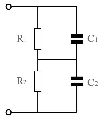
If you cannot find 500 VAC rated Y-type safety capacitors then you could consider using two capacitors in series. I would then also add a high value resistor (like 1 Mohm or more) in parallel with each capacitor to make sure the voltage is divided equally, like so:

enter image description here

Realize that you need resistors which can handle 250 V AC, the larger SMD types should suffice, for smaller types consider using two (or more) resistors in series to divide the voltage.

\$\endgroup\$
3
  • \$\begingroup\$ My application actually works with 35V max, so putting a X or Y capacitor may be an overkill. I recently found the source: johansondielectrics.com/ac-power-computations-for-dc-rated-caps As far as I understood, the graphs say that capacitance drops violently as AC voltage increases. While this may cause problems for a line filtering application, it works for my case. I would appreciate if you also checked the link and interpret the graphs. \$\endgroup\$
    – C K
    Commented Feb 11, 2019 at 12:10
  • \$\begingroup\$ My application actually works with 35V max Huh? Then where did the 500 VAC come from? You should be clear in your question what you need. \$\endgroup\$ Commented Feb 11, 2019 at 12:16
  • \$\begingroup\$ As I told in the question, the device is subjected to a dielectric test for certification, and for 35V rated operating voltage, it is 500VAC. \$\endgroup\$
    – C K
    Commented Feb 11, 2019 at 12:17

Your Answer

By clicking “Post Your Answer”, you agree to our terms of service and acknowledge you have read our privacy policy.

Not the answer you're looking for? Browse other questions tagged or ask your own question.