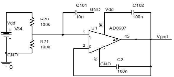
I'm following the design of a circuit requiring a power supply to provide something the author calls virtual ground, \$V_{gnd}\$. The circuit look like this:
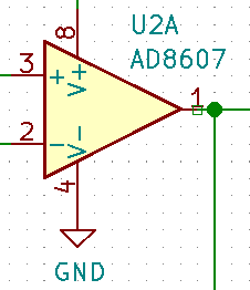
However, I'm using KiCad for the design and out of all the available power supply symbols, I can't find any that seem appropriate. I'm already using both the earth ground and common/signal ground symbols for something else. In fact, from that schematic, I can't even tell if that virtual voltage is negative or positive.
I have also looked at these relevant questions:
- Use of ground symbols in circuit diagrams
- What is the difference between \$V_{CC}\$, \$V_{DD}\$, \$V_{EE}\$, \$V_{SS}\$
- KiCAD 5 --- what is the significance of the various GND symbols?
- Why are power components meant to be power inputs in KiCad?
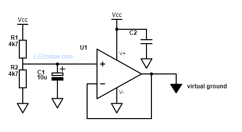
Apart from just labeling the network as the author does...
Q: What would be a more appropriate symbol to replace \$V_{gnd}\$?
PS. Is it just me, or is this diagram extremely sloppy? It seem very strange that some power networks terminate in mid air, while others are just labelled in-circuit without any termination. I can't imagine this is standard design practice.
UPDATE:


