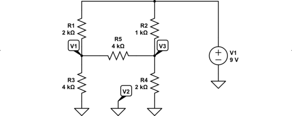
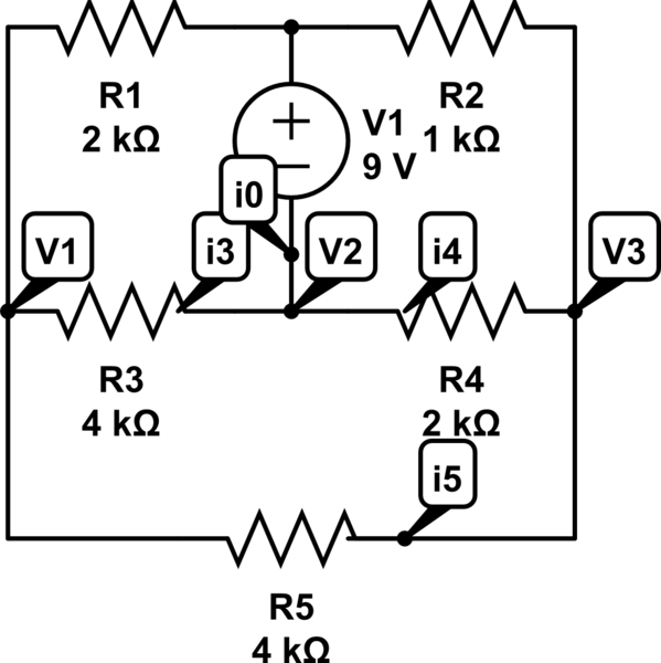
Sometimes, it helps to redraw the schematic:

simulate this circuit – Schematic created using CircuitLab
I've removed your indicators of current, since they are associated in an obvious fashion to the resistors and with \$I_0\$ associated with the voltage source's current. In re-drawing the schematic, I decided to make \$V_2\$ the ground reference. I've annotated that fact in the schematic, just to be pedantic about it.
As you can see, there are only two unknown voltages. So this means just two equations and two unknowns. In nodal form, this is just:
$$\begin{align*}
\frac{V_1}{R_1}+\frac{V_1}{R_3}+\frac{V_1}{R_5}&=\frac{9\:\text{V}}{R_1}+\frac{0\:\text{V}}{R_3}+\frac{V_3}{R_5}\\\\
\frac{V_3}{R_2}+\frac{V_3}{R_4}+\frac{V_3}{R_5}&=\frac{9\:\text{V}}{R_2}+\frac{0\:\text{V}}{R_4}+\frac{V_1}{R_5}
\end{align*}$$
You should be able to solve the above for \$V_1\$ and \$V_3\$. With those in hand, all of the currents are easily developed. (To read how I layout nodal, see the section called nodal, done my way.)
P.S. There is absolutely NO NEED for super-nodes. Certainly not in your circuit. But in general, not ever. I've no idea why anyone insists otherwise. (There never is a need, though of course you can use them if you like. No requirement, though. A topic for another day.) To me, supernodes inspire "tricky" thinking that can too readily lead to unintended errors in analysis. Different people will have different opinions. But no one can show that they are required. There is always an equivalent set of equations, more prosaic in nature and more easily developed, without using them.


