1
\$\begingroup\$

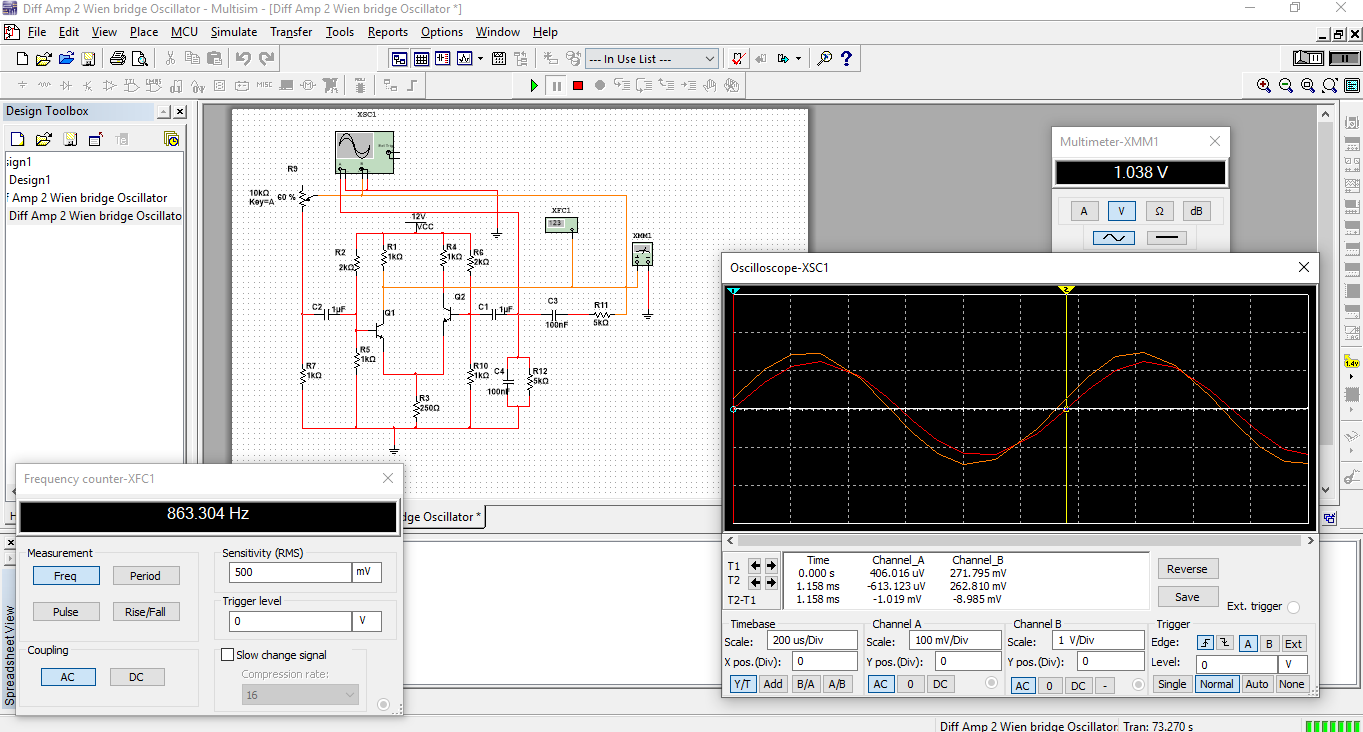
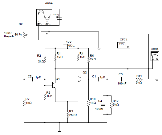
So I have created the attached Wien bridge oscillator using a transistor differential amplifier, the Negative gain is controlled using a potentiometer, center tapped and yes I understand that in the real world I would need to use an AGC to stabilise the output.

My problem is that the calculated frquency given the component should be,

f = 1/2picr = 1 / 2*3.141*10nF*5koHM = +-318.369Hz, But as you can see on the image, I'm getting something in the tune of +-863.04,

I have searched everywhere and I don't know what i'm doing wrong here, enter image description here

enter image description here

\$\endgroup\$
7
  • \$\begingroup\$ I meant the frequency should be 381Hz \$\endgroup\$ Commented Jun 13, 2019 at 4:34
  • 2
    \$\begingroup\$ edit your question above ... do not put information into comments \$\endgroup\$
    – jsotola
    Commented Jun 13, 2019 at 4:35
  • \$\begingroup\$ Are you sure that everything is connected at the C1/C3/C4/R12 junction? In general, it's better to offset the connections at a crossroads in multisim. \$\endgroup\$
    – Chu
    Commented Jun 13, 2019 at 7:53
  • \$\begingroup\$ Hi Chu, yes I'm quite sure their connected, If either parts were disconnected I don't think I would get any oscillation at all...the circuit does oscillate, but does it at the wrong frequency. \$\endgroup\$ Commented Jun 13, 2019 at 8:48
  • \$\begingroup\$ What is the purpose of R9 and R7 and C2 ?? This is an aditional negative signal feedback. \$\endgroup\$
    – LvW
    Commented Jun 13, 2019 at 14:33

1 Answer 1

0
\$\begingroup\$

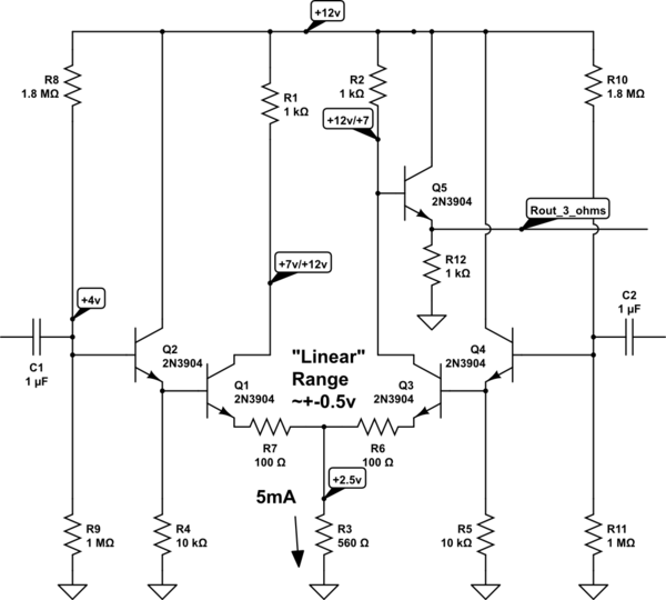
The diffpair is running at 12+mA. Rin (at the base) is about 400 ohms.

I doubt the coupling capacitors are sized for that low an impedance.

Also the 250 Ohm biases your transistors with very low Vce, so I'd increase that to 510 ohms (you can buy a 510 ohm).

Alter the circuit to be like this
schematic

simulate this circuit – Schematic created using CircuitLab

Rin will be approximately 500,000 ohms, up from 400 ohms.

Instead of "linear" range of diffpair being about +- 0.03 volts, this use of emitter-linearization (aka emitter degeneration, of the gain) provides +- Itail * Rem = +-0.5 volts.

=============== edit =====================

Added the 5th bipolar, to reduce Rout from 1Kohm to about 3 ohms. Rout is 1/gm or 1/(0.009/.026). The pulldown is still only 1K ohm. The pullup is very strong.

For moderate amplitudes, this circuit should give you VERY LOW distortion. The challenge is how to control the amplitude; you will need some nonlinearity, perhaps a series D+R across the negative feedback (actually back-to-back diodes, in series with a resistor that softens the nonlinearity)
\$\endgroup\$
5
  • \$\begingroup\$ Thank you for your comments, I increased R3 to 560Ohms. And while that gives me better amplitudes, my biggest problem is still the frequency, which is at 830Hz, whereas given the selection of components forming the Wien Bridge should be approx. 318.31Hz, Just to clarify I'm mostly concerned with the frequency of oscillations being so far off the expected value, even with tolerances taken into account, it's way far, \$\endgroup\$ Commented Jun 13, 2019 at 16:41
  • \$\begingroup\$ Notice the frequency LOWERED, toward what you predicted, when you increased the Rin of the DiffPair. Replace each transistor in the Diffpair with a 2-NPN Darlington. \$\endgroup\$ Commented Jun 14, 2019 at 2:05
  • 1
    \$\begingroup\$ Yep, Thank you, I increased the resistance to 1.5KoHM for the Tail and Collector resistances, which reduced Gain dramatically, but got the frequency right, so now I need to play around to see which combinations will give the best gain and then maybe get me some Darlington pairs, \$\endgroup\$ Commented Jun 14, 2019 at 5:47
  • \$\begingroup\$ you can use FOUR transistors, and make your own Darlingtons. \$\endgroup\$ Commented Jun 15, 2019 at 6:20
  • \$\begingroup\$ Xolani M.....Your calculation of the feedback network (Wien) completely ignores the input and output resistances of the transistors... \$\endgroup\$
    – LvW
    Commented Jun 15, 2019 at 9:13

Your Answer

By clicking “Post Your Answer”, you agree to our terms of service and acknowledge you have read our privacy policy.

Not the answer you're looking for? Browse other questions tagged or ask your own question.