1
\$\begingroup\$

enter image description here

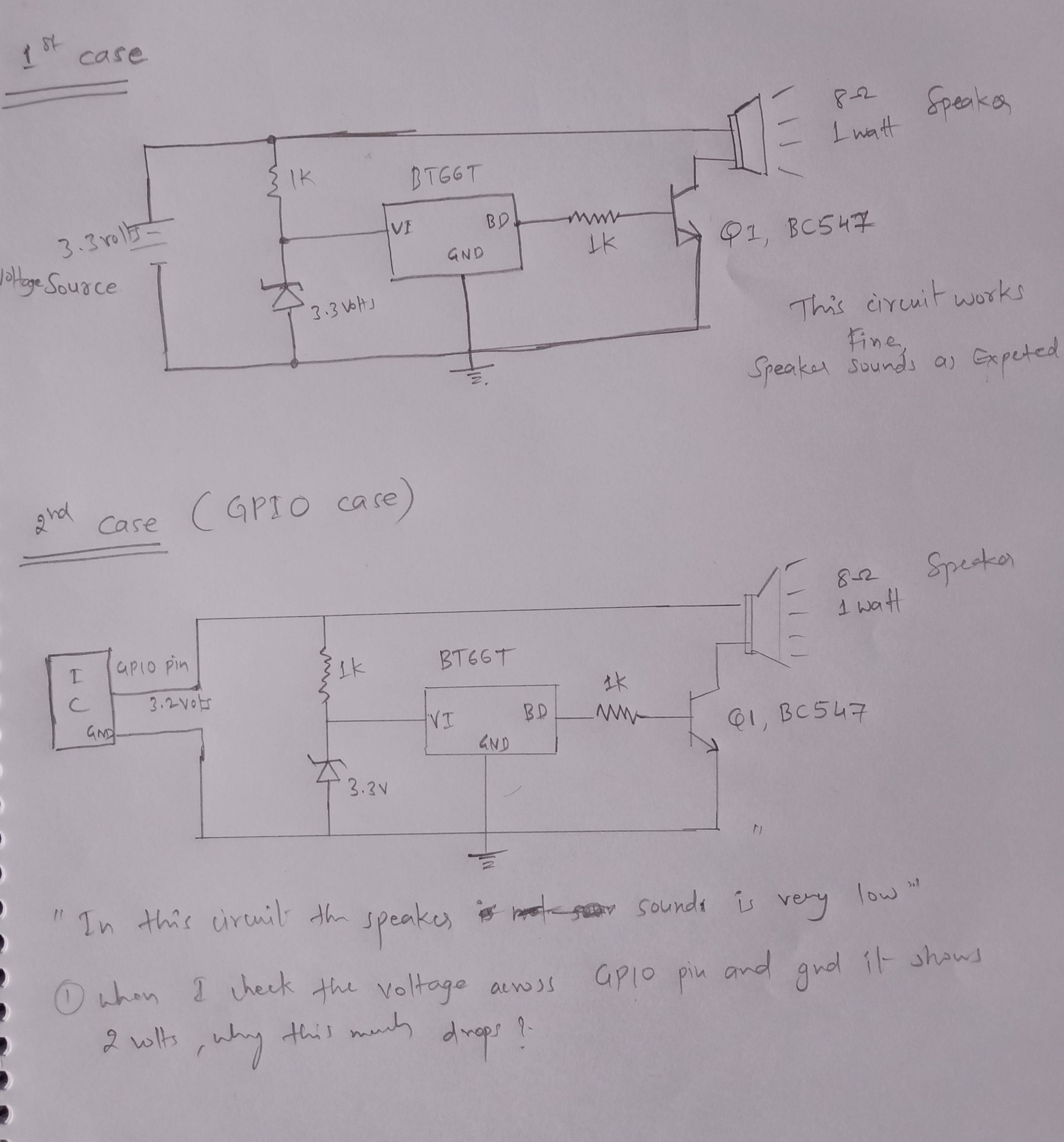
This circuit I am using to drive a speaker is acting strangely.

Case 1: When I connect the 3.3 volts source from the Nucleo board it works fine as expected (in terms of the sound.) When I check the voltage across source it is 3.1 to 3 volts. A drop of only .2 to .3 volts.

Case 2: When I connect the GPIO output pin 3.2 volts as a source to the circuit, the speaker sounds very low. When I check the voltage at the GPIO pin it is 2.1 to 2 volts. It drops nearly 1 volt.

Why is it dropping so much voltage? Due to this speaker does not sound as expected.

What is the issue? Can I resolve this?

Edit: The GPIO is from a BlueNRG-1 chip.

\$\endgroup\$
10
  • 1
    \$\begingroup\$ What is "nuclei board" and what GPIO pin are you talking about? And "connecting " it , where? This post is very confusing. \$\endgroup\$
    – niko20
    Commented Jan 6, 2021 at 6:20
  • 2
    \$\begingroup\$ "When i connect the GPIO output pin 3.2 volts as a source to the circuit". You don't show a device with a GPIO pin in your circuit diagram. Generally, GPIO pins do not provide much current. Not only may you not get much sound, you may damage the component with the GPIO pin. \$\endgroup\$ Commented Jan 6, 2021 at 6:25
  • 1
    \$\begingroup\$ This is just the circuit from the BT66T datasheet. You need to show how you have connected your nucwhatever board. \$\endgroup\$
    – copper.hat
    Commented Jan 6, 2021 at 6:41
  • 1
    \$\begingroup\$ Thank you for the new picture, but it still is not clear what component or board the GPIO is a pin of. Without knowing what the IC or board is, I cannot tell whether you are attempting to use more current from it than it is capable of. My guess is that you are, and that you will not only get poor volume, but may be damaging your IC or board. \$\endgroup\$ Commented Jan 6, 2021 at 7:19
  • 1
    \$\begingroup\$ GPIO pin on a RPi is only good for 16 mA. You cannot use it to supply power to the rest of your circuit directly and you may damage the GPIO with this arrangement. \$\endgroup\$
    – mhaselup
    Commented Jan 6, 2021 at 7:22

4 Answers 4

10
\$\begingroup\$

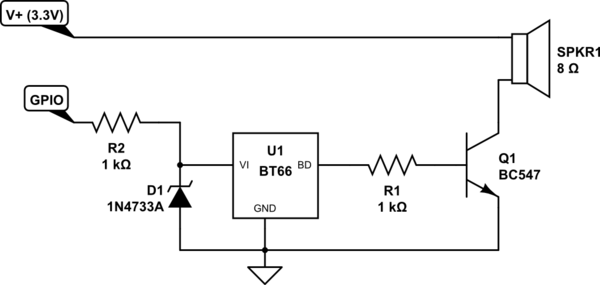
You need to do something like this:

schematic

simulate this circuit – Schematic created using CircuitLab

That delivers power to the speaker as needed, but allows you to turn on the BT66 (which seems to be an FM radio receiver) with the signal from your GPIO pin.

As has already been noted, IO pins from microprocessors aren't intended to provide power. They are control or data signals, and cannot provide high current.


The above sketch assumes that the BT66 is powered from something appropriate. You didn't show the power connections for it in your sketches, and I didn't make an effort to find a datasheet or other description of it.

\$\endgroup\$
1
  • \$\begingroup\$ Hi JRE, how can we increase volume? in this circuit. \$\endgroup\$
    – GKN
    Commented Jan 25, 2021 at 4:45
5
\$\begingroup\$

The issue is that you assume that a GPIO pin is a strong output like a power supply, but it isn't.

The speaker is an 8 ohm load that would take more than 400mA when connected to 3.3V. That would consume about 1.36 watts.

A typical GPIO pin is much weaker, they typically can provide up to 20mA without getting permanent damage, and even that with reduced output voltage.

So expecting a GPIO to drive an 8 ohm load won't work. You need to drive a transistor or other amplifier with the GPIO pin, and use the transistor or amplifier to drive the speaker.

\$\endgroup\$
4
\$\begingroup\$

A GPIO pin isn't intended to power circuits. It's a logic output for signalling to other devices, or to turn on a transistor. To a GPIO pin, an 8 ohm speaker is pretty much a short circuit.

Use the GPIO to turn on a transistor, which then powers the rest of the circuit.

\$\endgroup\$
2
\$\begingroup\$

The main issue (even though the details of the circuit are unclear) is that the GPIO pin isn’t sourcing enough current to drive the BT66T. You may be able to resolve it by buffering the GOIO pin. A simple approach would be to use a general-purpose p-channel FET, connect the gate to the GPIO pin, drain to your 3.3V supply and source to the VI pin of the BT66T. Then drive the GPIO pin low to activate it. Be sure to choose a FET with a low threshold voltage of about 2V.

\$\endgroup\$
5
  • \$\begingroup\$ It is not the BT66T that needs that much current, it is the speaker. It has 8 ohms. \$\endgroup\$ Commented Jan 6, 2021 at 12:04
  • \$\begingroup\$ At the time of writing The speaker was shown driven off a 9V supply \$\endgroup\$
    – Frog
    Commented Jan 7, 2021 at 6:43
  • \$\begingroup\$ But the OP clearly stated that the circuit (as a whole) was sourced from the GPIO. -- The first hit on any web search reveals the description of the BT66T, which gives its supply current as 1µA. So it's still not the IC, you might call the resistor-zener combination to have a "high" current. I expect at least a little bit of thinking and research. \$\endgroup\$ Commented Jan 7, 2021 at 7:06
  • \$\begingroup\$ The question has been updated at least once since I responded to it. \$\endgroup\$
    – Frog
    Commented Jan 7, 2021 at 7:51
  • \$\begingroup\$ I know. I looked at the very first version, and any after it. My claim still holds true. \$\endgroup\$ Commented Jan 7, 2021 at 7:52

Your Answer

By clicking “Post Your Answer”, you agree to our terms of service and acknowledge you have read our privacy policy.

Not the answer you're looking for? Browse other questions tagged or ask your own question.