1
\$\begingroup\$

I've built a flyback transformer by hand for a circuit I am making and after shorting the secondary I have found my leakage inductance is very high. The primary inductance is around 2 mH, while the leakage inductance is at 1.3 mH and it is supposed to be at max only 60 uH. I have made the transformer twice now with the same result and I can't figure out what is going on.

Primary turns: 143

Secondary turns: 6 trifilar

As requested I am providing more detail. My primary inductance is calculated by:

$$ Lp = Vin^20.5*Duty*eff/(Po*fs) $$

Vin = 135V, Duty=0.636, eff=0.72, Po = 10W, fs =137kHz

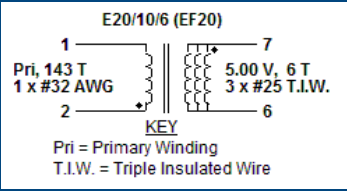
I need to have a target primary inductanced around 1900-2000 uH, and so I need to used a gapped core. The transformer construction given by PI designer is. Note there are 3 layers of tape between primary and secondary.

enter image description here.

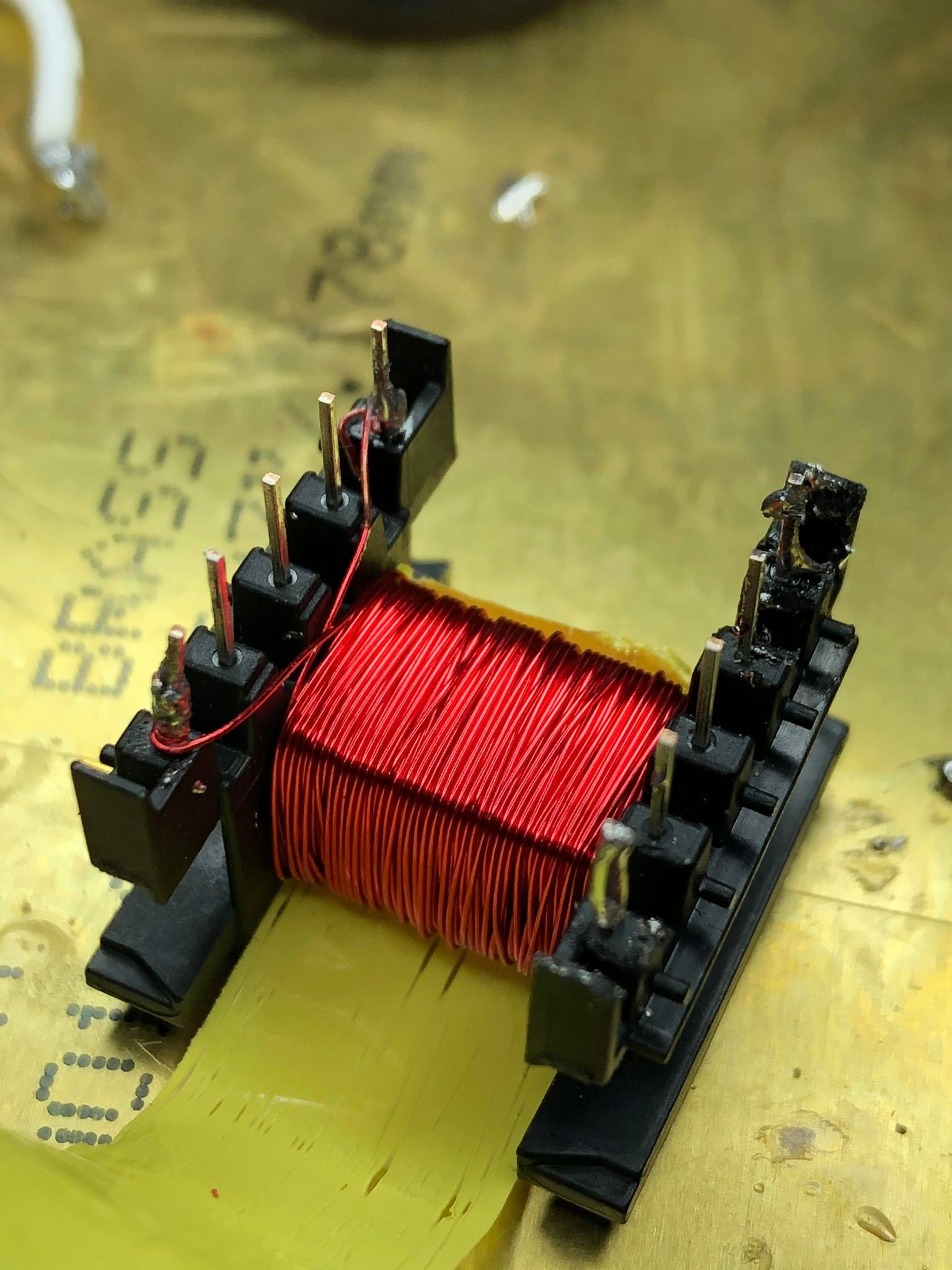
My Primary winding looks like this: enter image description here

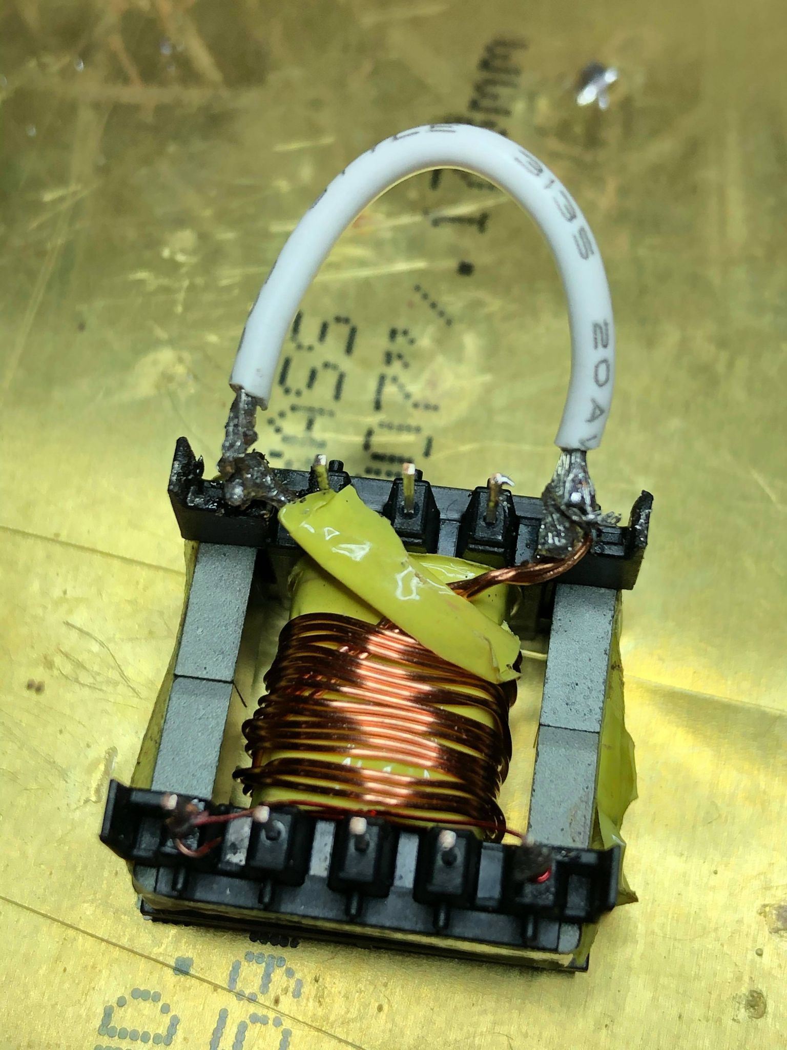
Shorted secondary to measure leakage: enter image description here
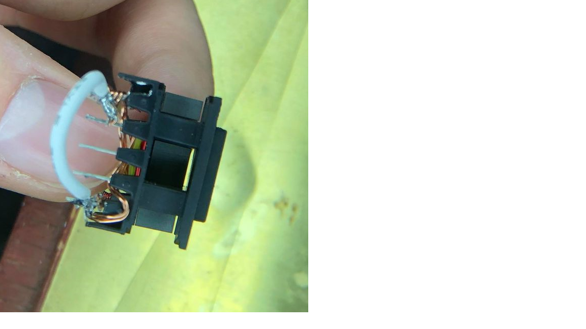
Picture of core inside bobbin, there is a slight gap at the top which could potentially contribute: enter image description here
The core material I am using is N27, core is gapped 0.17MM (recommended core gap from PI is 1.2 mm. Here is the data sheet The measurement was made on Proster 3M4070 LCR meter, accuracy should be off by roughly +/- 5 uH. The wires used for the core were not triple insulated, they are some wires I got off Amazon from BNTechGO

\$\endgroup\$
10
  • 4
    \$\begingroup\$ You would have to show the details of your construction for anyone to have any chance at answering that. A picture and a diagram of how the windings are wound with dimensions would be helpful. It certainly sounds like incredibly high leakage so you may want to add exactly how you made the measurement. \$\endgroup\$
    – John D
    Commented Feb 14, 2021 at 3:21
  • \$\begingroup\$ Only 80% coupling? No core or capped. \$\endgroup\$
    – D.A.S.
    Commented Feb 14, 2021 at 3:46
  • \$\begingroup\$ I think that the volume of copper should be the same for both windings for best coupling (same # of Cu atoms). If you are using the same guage for primary and secondary, then with 143 turns on the primary, then the secondary should have 6 turns of 24-filar winding. Or 6x3x8 alternatively 8 paralleled windings of 6 trifilar. But that's only if you are using same thickness wire throughout, I believe. \$\endgroup\$ Commented Feb 14, 2021 at 4:18
  • 1
    \$\begingroup\$ ”Secondary turns: 6 trifilar” From the look of it, it’s 3xsome wire guage in parallel, but it’s not trifilar. Try to wind it bifilar, usually with half of your primary turns, tape and margin tape, secondary turns, tape gain and then the remaining half of your primary turns. \$\endgroup\$
    – winny
    Commented Feb 14, 2021 at 18:47
  • 1
    \$\begingroup\$ At this point I'm not sure why your leakage is so high, but @winny's suggestion of interleaving the secondary and primary usually helps. Transformer design is often an iterative process. \$\endgroup\$
    – John D
    Commented Feb 14, 2021 at 19:32

1 Answer 1

2
\$\begingroup\$

the main cause of high leakage inductance is too much separation between the primary and secondary windings. But please provide more details, such as a picture of the cross section, what's the core material, is it gapped, etc.

\$\endgroup\$
1
  • \$\begingroup\$ Hello, I have updated the post with additional details. \$\endgroup\$
    – willieb3
    Commented Feb 14, 2021 at 18:17

Your Answer

By clicking “Post Your Answer”, you agree to our terms of service and acknowledge you have read our privacy policy.

Not the answer you're looking for? Browse other questions tagged or ask your own question.