1
\$\begingroup\$

Everybody knows what a "current to voltage" converter is, a basic application configuration for op amps.

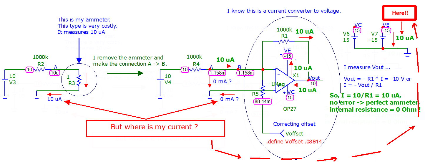
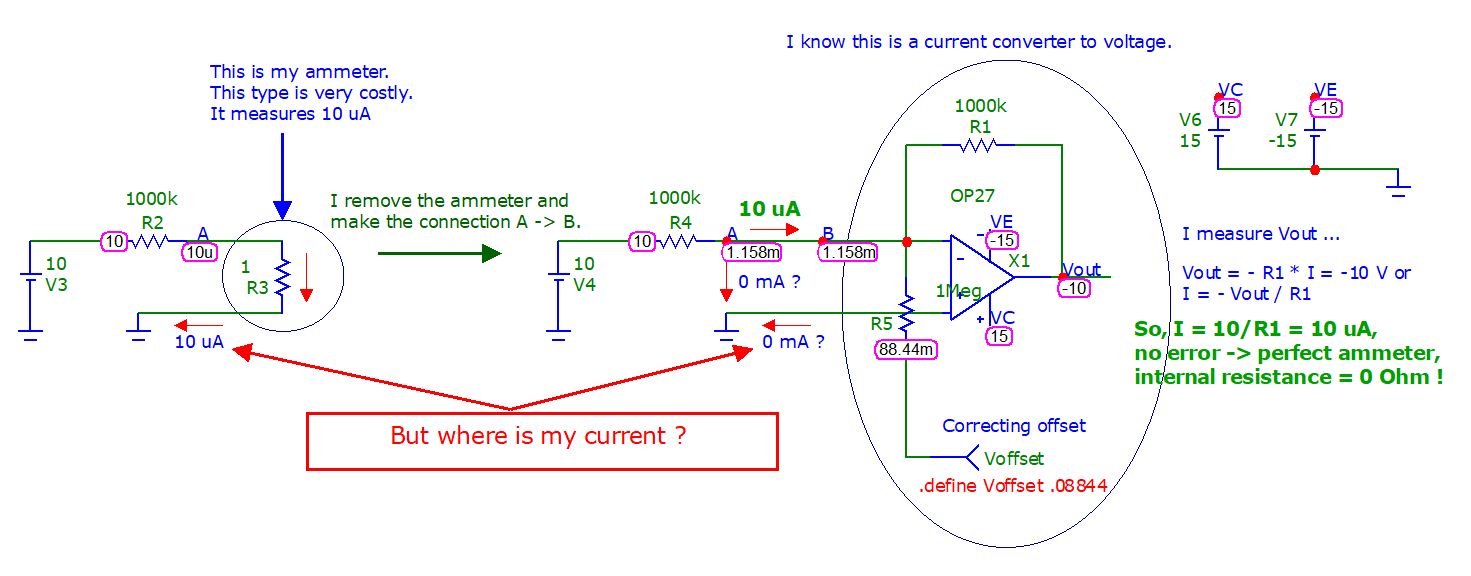
This is a very level basic question. See the picture. What is wrong? Have I missed something?

OP27 link.

enter image description here

Just to emphasize the importance of ("hidden" or not) wiring ...

\$\endgroup\$
6
  • \$\begingroup\$ Why are you pointing at the (+) op amp input node with respect to a current there. Do you expect one that matches your earlier measured current? \$\endgroup\$
    – jonk
    Commented Sep 7, 2021 at 18:52
  • \$\begingroup\$ Yes ... I am a "newbie". Because of the way I wire the current-voltage converter. I "expect" 10 uA in the wire (+) op amp to ground. \$\endgroup\$
    – Antonio51
    Commented Sep 7, 2021 at 18:58
  • \$\begingroup\$ No. You should expect an bias current from that op amp input. But otherwise unrelated to the current you are injecting at the other input. The other input itself may also have its bias current, too (and it will since it must in order to work.) This last aspect will confound your transimpedance design a bit, too. I recommend that you study the input stage of your given bipolar op amp. \$\endgroup\$
    – jonk
    Commented Sep 7, 2021 at 18:59
  • \$\begingroup\$ Ok for the current flowing in R4 ... and R1. Ok also for the bias input current (almost 0 nA) that flows between (+) and ground. But "where" is my 10uA that flows in the picture at left ? How can one rewire this schematic to see these 10 uA ? \$\endgroup\$
    – Antonio51
    Commented Sep 7, 2021 at 19:02
  • \$\begingroup\$ Thanks for the correction. I mispoke when I wrote "offset." I meant bias! (Edited and fixed!) Each input has its bias current. The schematic on page 2 illustrates why it must. They also have an offset (difference between them.) In the ideal case, there would be zero bias and zero offset currents and no voltage offset, either. The idea for your current to voltage converter is that the output must slew in order to pull away the current you inject into the node (plus or minus whatever bias current the input causes.) But that has no never-mind with respect to the other op amp input bias current. \$\endgroup\$
    – jonk
    Commented Sep 7, 2021 at 19:03

7 Answers 7

2
\$\begingroup\$

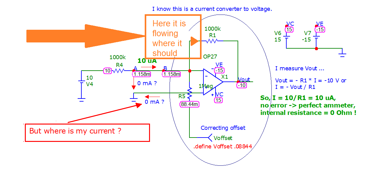
This shows where all the current flows and how the 10uA finds it's way back to your ground connection:

enter image description here

For the op amp output to sink the 10uA of current, it has to send it down the negative supply pin, hence it returns to your source via the ground connection of the negative supply.

If you put in a negative voltage (V4 < 0) so that the current flows the other way, then the output goes positive to drive the current back through the feedback resistor, and this current is sourced from the positive supply (V6) and is returned to your voltage source via it's ground connection.

\$\endgroup\$
5
\$\begingroup\$

schematic

simulate this circuit – Schematic created using CircuitLab

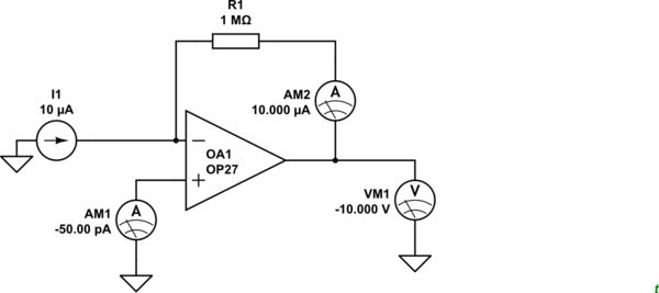
Figure 1. I1 doesn't go into the inverting input due to its high impedance. It goes through the feedback resistor, R1.

The current from the non-inverting input is just the bias current and has little, if anything, to do with the current on the inverting input.

\$\endgroup\$
4
  • \$\begingroup\$ Perhaps show the shunt Rs = 1 Ohm resistor going to ground with a series R with 10uV across it , then getting amplified to 10 V needs a lot of gain. You are missing the simulation of 10V/1M direct into a shunt R but rather showing the gain of -1 from +10V input to -10V output. So it is Voltage gain with Ohm's Law. \$\endgroup\$
    – D.A.S.
    Commented Sep 7, 2021 at 20:49
  • \$\begingroup\$ also point out the Iin x mismatched R created the offset. \$\endgroup\$
    – D.A.S.
    Commented Sep 7, 2021 at 20:55
  • \$\begingroup\$ @Tony, there is no shunt in the OP's op-amp circuit. I've just used the 10 V source through 1M into virtual ground represented by the 10 uA current source. What do you think I've missed? \$\endgroup\$
    – Transistor
    Commented Sep 7, 2021 at 20:58
  • \$\begingroup\$ You didn't missing anything except an opportunity to correct what the OP missed in simulating the meter with an Op Amp \$\endgroup\$
    – D.A.S.
    Commented Sep 7, 2021 at 21:12
3
\$\begingroup\$

enter image description here

That's basically how a transimpedance amplifier works; the output keeps the inverting node at the same voltage as the non-inverting node. The output takes that current (or drives that current if you prefer). The input impedance of the OP27 is a gazillion ohms. However, the OP27 does have input bias currents of circa 100 nA and these might pose a significant error if it's important.

\$\endgroup\$
2
\$\begingroup\$

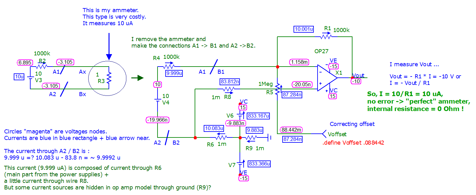
I have redraw a little my schematic to show where this current is "gone".

It is a great part of the answer, but it lacks "something".

Remember that we are in "simulation" and that some currents sources are hidden in the model of op amp we use.

So the answer is not "complete". I think the true answer is in the "laboratory" where we can measure really everything (not always simple).

For adjusting "offset", make V4 = 0 in microcap v12 "schematic", click on "Dynamic DC", click on "define Voffset ..." then change through arrows up or down until Vout is nearest 0 V. Then remake V4 = 10 V.

enter image description here

\$\endgroup\$
2
\$\begingroup\$

Your current will not emerge from the non-inverting input, because of the high input impedance. For the same reason, no current will enter the inverting input. This is the path that your input current will take:

enter image description here

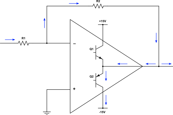
Q1 and Q2 represent the push-pull output stage of the opamp. Note that current will branch at the output of the opamp, some to be sunk by the opamp itself via Q2, and some will be sunk by whatever load you connect to the output.

The input current emerges at the negative supply pin of the opamp. The current emerging there will also include the opamp's own operating current, as well as the input current being "measured".

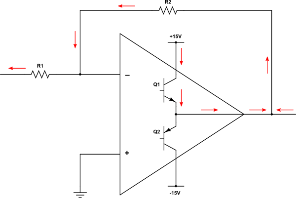
If the input current is negative (in the opposite direction) it will follow this path instead:

enter image description here

This time the opamp (and whatever load you have connected) will be sourcing current for the input to sink.

\$\endgroup\$
2
  • \$\begingroup\$ Exact answer! It only remains to be seen what the hell this is all about? Why is it done that way? \$\endgroup\$ Commented Dec 24, 2021 at 9:45
  • \$\begingroup\$ Just to add a "small" correction - the load current flows in the opposite direction. For example, when the output voltage is negative (your first picture), the op-amp sinks both the input and load current. In this case, the load current is entirely determined by the negative power supply while the input current is determined both by the positive input voltage source and the negative power supply (they are connected in series so that their voltages are added). \$\endgroup\$ Commented Dec 24, 2021 at 15:01
2
\$\begingroup\$

The necessary philosophy

I read these answers full of technical details and wonder how it is possible not to reveal the simple but brilliant idea behind this op-amp circuit consisting only of a resistor and op-amp? I realized it 30 years ago (Fig. 1) and with its help I was able to understand and explain many other op-amp circuits.
Voltage compensation - an old idea from 1992

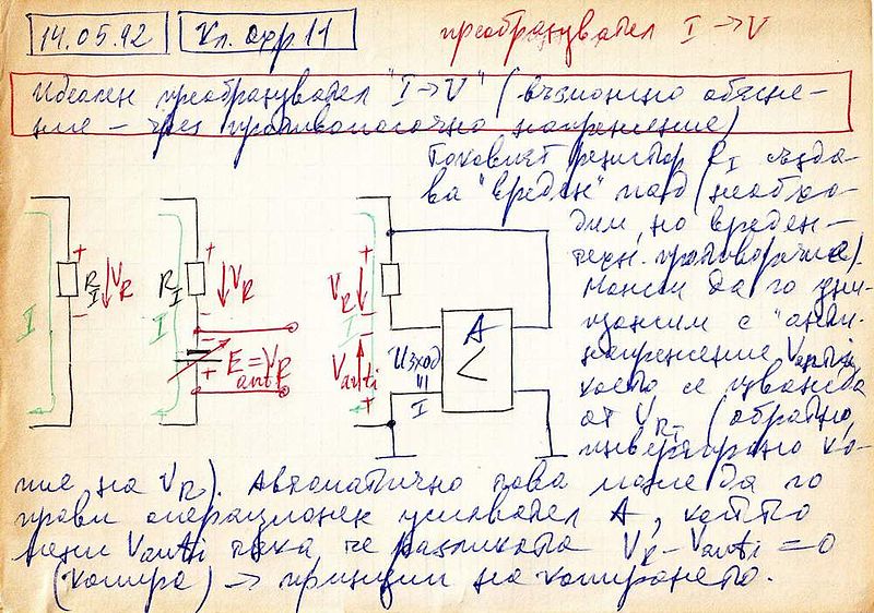
Fig. 1. A conceptual picture of an active current-to-voltage converter from my archive (1992). Here is the translated text:

May 14, 1992. "Ideal" current-to-voltage converter (a possible explanation by an opposite voltage). The current-sensing resistor RI creates a "harmful" voltage drop VR (it is necessary but undesired; there is a contradiction). We can destroy it by an "anti voltage" V(E)anti that is subtracted from VR (it is an inverse copy of VR). It can be implemented by an op-amp A that adjusts Vanti so that VR - Vanti = 0 ("active copy" principle).

Basic idea

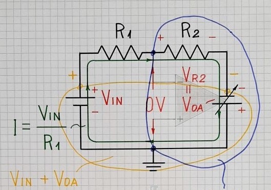
The idea is obvious: To measure the current I by a voltmeter, we break the circuit, insert a resistor RI and measure the voltage drop across it (VR = I.RI). But this voltage introduces an error since it is subtracted from the input "current-creating" voltage VIN and the current decreases. So we decide to destroy it by adding an equivalent voltage V = VR. For this purpose, we break again the circuit and insert a varying voltage source producing the compensating voltage V. This voltage is added to the input voltage and the error is eliminated - Fig. 2.
Transimpedance amplifier - full conceptual circuit

Fig. 2. Full conceptual circuit of four elements in a loop (the picture is taken from a similar story about the inverting amplifier). Note the two voltages are summed in a series manner.

Op-amp implementation

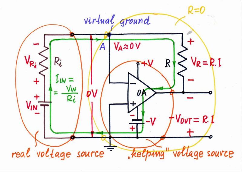
So the (properly supplied) op-amp output acts as a small variable "battery" connected in series to the resistor (Fig. 3) that adds the compensating voltage VOUT = I.R in the circuit. And, of course, the input current will flow through this "battery".
Transimpedance amplifier

Fig. 3. Op-amp implementation of the idea

To close the current path, we have to draw the respective power source - negative if the input voltage is positive (like in Fig. 3) and positive if the input voltage is negative.

How does the op-amp do it?

It is interesting to see how the op-amp copies the voltage drop VR at its output. According to KVL, we can see in Fig. 2 and Fig. 3 a loop of three voltages - VR, VOUT and VA. The op-amp changes VOUT so that to keep VA zero (negative feedback). As a result, VOUT = VR.

Another clever trick is that we use the compensating voltage as a buffered, grounded and inverted output voltage (the last feature is a "gift" that is not always desired).

Visualized operation

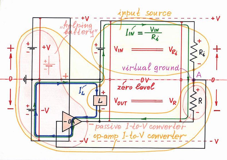
To illustrate the circuit operation in a more attractive way, we can "geometrically" draw the circuit diagram - Fig. 4.
Transimpedance amplifier visualized

Fig. 4. A "geometrical" representation of the op-amp current-to-voltage converter

In this representation, the "positive circuit part" is drawn above the zero voltage level (ground) and the "negative circuit part" is drawn below the ground. The voltages are represented by voltage bars in red and the currents - by current loops in green and blue.

Note something very important - the input current (in green) does not flow through the load. The load current (in blue) is provided only by the negative supply source, i.e., the load does not consume current from the input voltage source. This is a big advantage of the active op-amp circuit compared with the passive one (resistor).

Circuit evolution

The power of this step-by-step building approach is that it shows the circuit evolution from the humble 1-resistor passive circuit to the more sophisticated op-amp circuit. We see this is not a new circuit; it is an improved old circuit. So the active op-amp current-to-voltage converter consists of a passive current-to-voltage converter and helping op-amp.

Negative resistance viewpoint

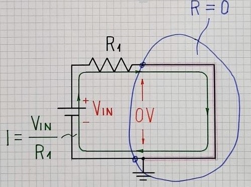
If we are curious enough, we can see a similarity between the resistor R and the op-amp output - there is the same voltage I.R across them; so both behave as resistors. But while the resistor subtracts its voltage drop from the input voltage, the op-amp adds its output voltage to it.

So the op-amp output acts as a negative "resistor" with resistance -R that neutralizes the positive resistance R. The whole circuit (resistor and op-amp) behaves as a "piece of wire"... and the input current flows through this "artificial wire" - Fig. 5.
Transimpedance amplifier as a piece of wire

Fig. 5. The transimpedance amplifier presented as a "piece of wire"

Passive vs active version

As a rule, we know the passive is bad and the active is good. But here the passive "circuit" (resistor) has a very significant advantage over the active - it allows to measure currents of large magnitude.

The problem with the active op-amp current-to-voltage converter is that the current passes through its output stage... and the latter must withstand it. That is why the ammeters inside multimeters are not made with the op-amp circuit, no matter how perfect it is, but with the simple passive circuit (a humble resistor between the inputs).

\$\endgroup\$
6
  • 1
    \$\begingroup\$ Anyway, interesting view of current-voltage converter ... \$\endgroup\$
    – Antonio51
    Commented Dec 24, 2021 at 22:48
  • 1
    \$\begingroup\$ My answer shows clearly that current flows from ground ... from power supply, which is also connected to +input of the op-amp. \$\endgroup\$
    – Antonio51
    Commented Dec 24, 2021 at 22:55
  • \$\begingroup\$ @Antonio51, Thank you! It is so rare for our ideas to be appreciated here... the environment is very selfish and that keeps us from giving our best... Admittedly, I wrote this story especially for you because I felt something different that deserves more than a formal (soulless) answer... \$\endgroup\$ Commented Dec 24, 2021 at 22:56
  • 1
    \$\begingroup\$ Thank you also. I solved this problem in 1969 (first year of electrical engineering, the exercise of general electricity where op-amp was just a Voltage to voltage amplifier with infinite gain. \$\endgroup\$
    – Antonio51
    Commented Dec 24, 2021 at 23:02
  • 1
    \$\begingroup\$ @Antonio51, It is better not to mention the positive input, because it has nothing to do with the idea. Years ago, these circuits were made with single-ended inverting amplifiers that had no positive input at all. BTW I had a feeling you knew the answer to the question before you asked it... and maybe you just wanted to share it? If so, there is nothing wrong with that, although not everyone here accepts it that way... \$\endgroup\$ Commented Dec 24, 2021 at 23:03
1
\$\begingroup\$

The input current does not go through the feedback resistor. It is nullified by current coming backwards through the feedback resistor from the output. OK, the two resistors do look like a voltage divider between two different potentials, so in one sense the input current does go to the output.

But . . .

The opamp has lotsa gain, and the action of negative feedback drives the inverting input to behave as a virtual ground. This changes the analysis of the circuit. the two resistors do form a voltage divider, but having a point in the middle of the divider that does not move breaks that current into two related but not in the same way currents. The output does whatever it takes to make the two input voltages equal, so whenever the loop is closed, the two currents are equal. But they are not in the same direction.

In your case the two resistors are of equal value so the conversion factor through the circuit is 1 volt per amp. If R4 were 100 K, the conversion would be 10 V per amp, but the two currents still would be the same value, and the net current at the inverting input still would be 0.

Note, all of this assumes a theoretically perfect opamp with zero input bias current and zero input offset voltage.

\$\endgroup\$
2
  • \$\begingroup\$ Interesting... This is a possible but still formal explanation that would please someone living in the fictional world of circuit theory. But I live in the real world where I see a closed circuit in which only one current I = (Vin + Vout)/(R1 + R2) circulates. \$\endgroup\$ Commented Dec 25, 2021 at 16:14
  • \$\begingroup\$ But to be honest, I have to admit that I have thought of this circuit many times as two interacting sources, each producing its own current. But eventually the midpoint voltage is established and the equilibrium is reached. \$\endgroup\$ Commented Dec 25, 2021 at 16:15

Your Answer

By clicking “Post Your Answer”, you agree to our terms of service and acknowledge you have read our privacy policy.

Not the answer you're looking for? Browse other questions tagged or ask your own question.