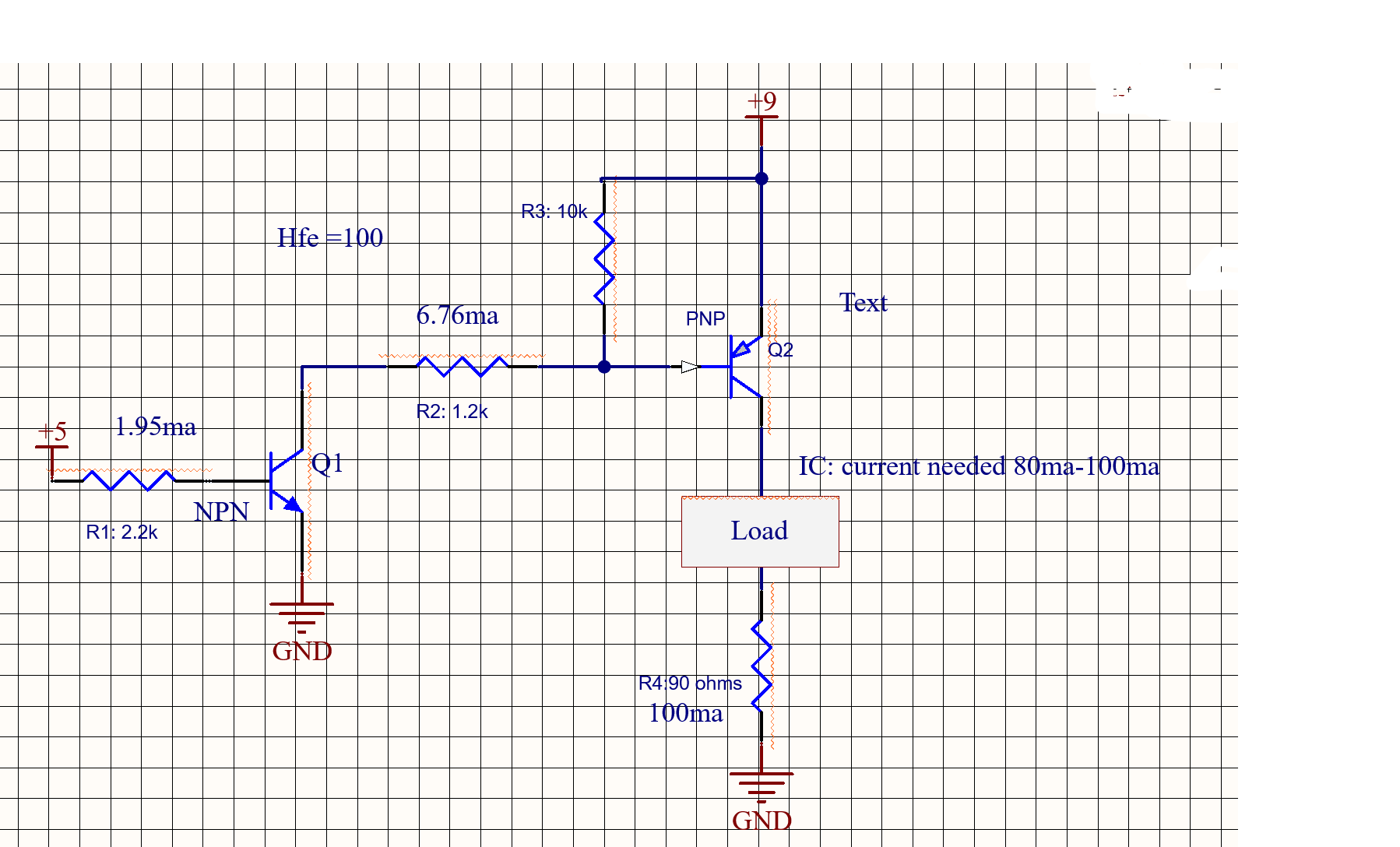
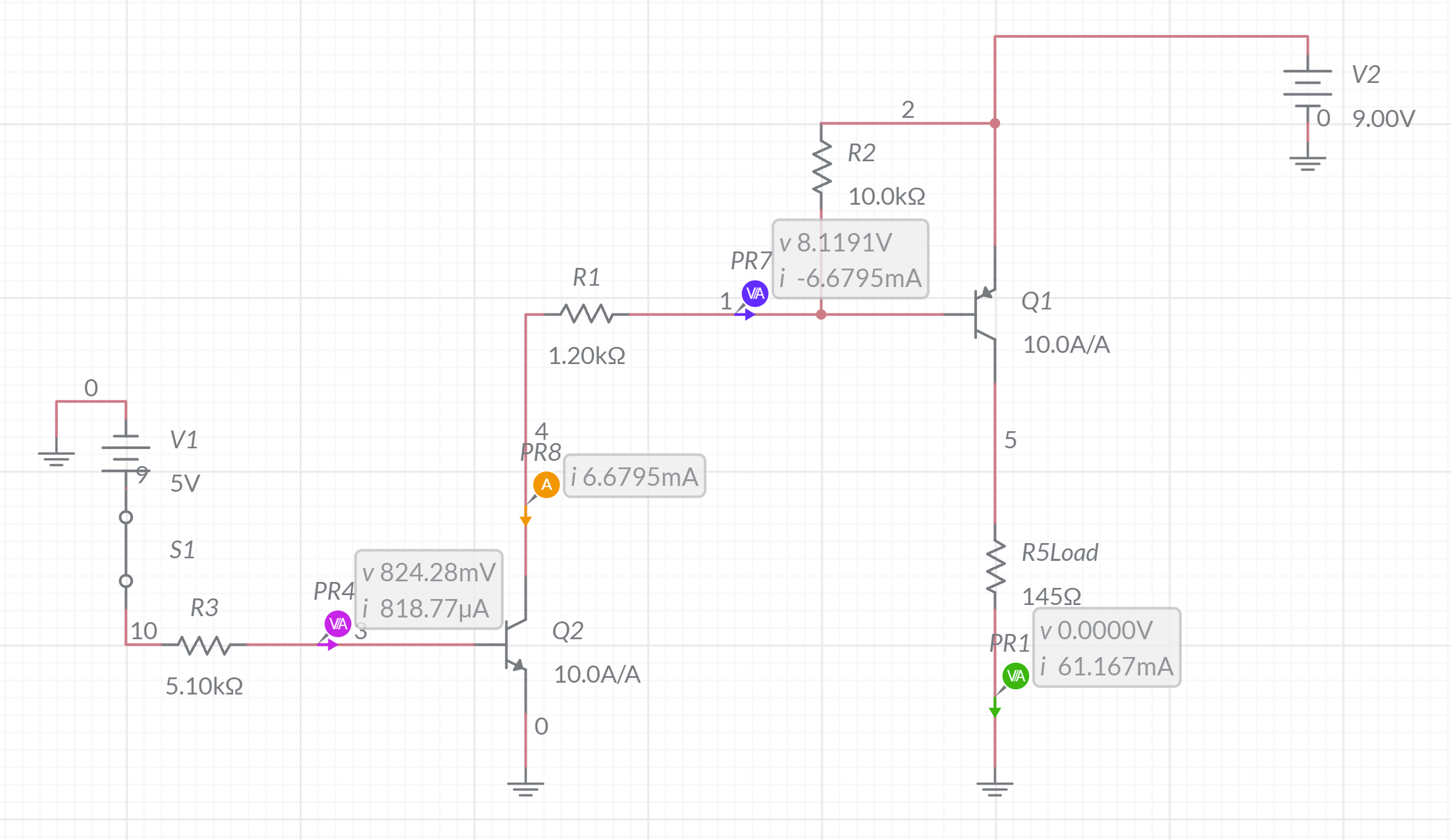
In my circuits below, I'm using a NPN 2N2222 and PNP MMBT2907A, I implemented this high side switch circuit and it works. However, I'm very concerned about the resistor values that I used. In my first circuit, I place a R1=2.2k and R2=1.2k at the transistors' bases, but after reviewing a similar question form here high-side-switch-24v-6ma-control-by-arduino I change my resistor values in my 2nd circuit with R1= 5.1K and R2=1.2K. Here's the math behind these values. If we allow the base current to be Ic/Ib = 10 and the collector current at the PNP needed is about 60ma-70ma, I would need at least 6ma at the base of the PNP transistor thus R2 must be about 1.2K. Now we have about 6ma-7ma on the NPN IC current, therefore a base current must be about .6ma-.8ma, thus I used a R1=5.1K resistor value. I was wondering if any one can tell me is that the above configuration is correct and that the circuit can be used safely. Thank you so much!
-
3\$\begingroup\$ You may have a few odd ideas about how BJTs work. \$\endgroup\$– jonkCommented Oct 10, 2021 at 3:13
-
1\$\begingroup\$ ""we know that at 700ma the transistor will stop functioning," This is wrong. Start from the beginning. \$\endgroup\$– DKNguyenCommented Oct 10, 2021 at 4:40
-
\$\begingroup\$ DKNguyen what I mean is that if a transistor max IC=600ma, if we allow more current than 600ma the transistor might stop working \$\endgroup\$– CitiCommented Oct 10, 2021 at 5:27
-
\$\begingroup\$ Beta, the gain of the transistor, varies quite a bit. There can be differences from unit to unit. Differences with temperature. Differences with collector current, etc. It is not good to assume that beta is a specific number. You have to design your circuit so it works over a range of Beta values. \$\endgroup\$– user57037Commented Oct 10, 2021 at 6:33
-
\$\begingroup\$ mkeith Yes, I need to figure out how to design my desire circuit using the smd's NPN 2N2222 and PNP MMBT2907A transistors to account for Beta values, and still get at least 100ma in the PNP IC current. \$\endgroup\$– CitiCommented Oct 10, 2021 at 6:59
1 Answer
When you are using a BJT as a switch (and not just as an analog amplifier), you will usually have a base current more than the minimum needed. That's not really driving it hard.
For the 2N2222 in particular, the max base current is 200mA. See https://html.alldatasheet.com/html-pdf/15067/PHILIPS/2N2222/745/3/2N2222.html
That would be absolute max. I wouldnt go more than 2X or 3X the needed current, unless there's a very good reason. So, at 500mA collector current, assuming gain of 100, that would be about 10-15 mA base current.
Also keep in mind, the max power dissipation of the package and the ambient conditions you'll have the transistor in. If you're in the 2X range, it shouldnt be much of an issue, considering that the collector current is the max contributing to the power dissipation. If you are going more than 3X, you now have significant power dissipation to consider.
-
\$\begingroup\$ Thank you for your answer. I see how allowing more current at the base is not really driving hard. Yes, what I'm concern about is that using low resistor values at its bases will affect the power dissipation. I only need at least 100ma at the PNP Ic current, so I might change the resistor values to R1=10k and R=4.7K \$\endgroup\$– CitiCommented Oct 10, 2021 at 5:37
-
\$\begingroup\$ @Citi, if you're concerned about the power contribution from the base current, consider just using a MOSFET instead of a BJT. \$\endgroup\$ Commented Oct 10, 2021 at 15:56
-
\$\begingroup\$ The datasheet for every transistor shows that hFE is used when the transistor always has plenty of Vce as an amplifier. It shows a base current of 1/10th the collector current (regardless of hFE) when the transistor is used as a saturated switch because then the Vce is very low. \$\endgroup\$ Commented Oct 10, 2021 at 16:00
-
\$\begingroup\$ Yes, I used the transistors to implement a high side switch, I updated my question, keeping in mind the 1/10th collector current. I was wondering if someone can tell me if my worked values are good and understandable to use. thank you for your help \$\endgroup\$– CitiCommented Oct 10, 2021 at 21:35
-
2\$\begingroup\$ When using a transistor as a saturated switch, the goal is usually to run the base at 1/20th or 1/10th of the desired collector current. This helps insure that Vce will be low. To say it another way, instead of assuming a gain of 100, assume a gain of 10 or 20 at the most. \$\endgroup\$ Commented Oct 10, 2021 at 21:36


