1
\$\begingroup\$

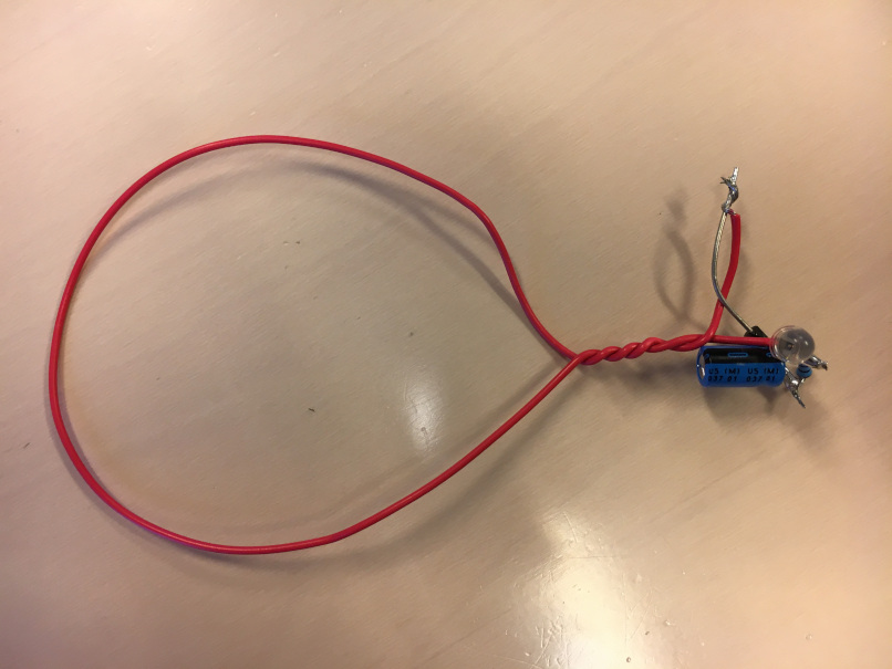
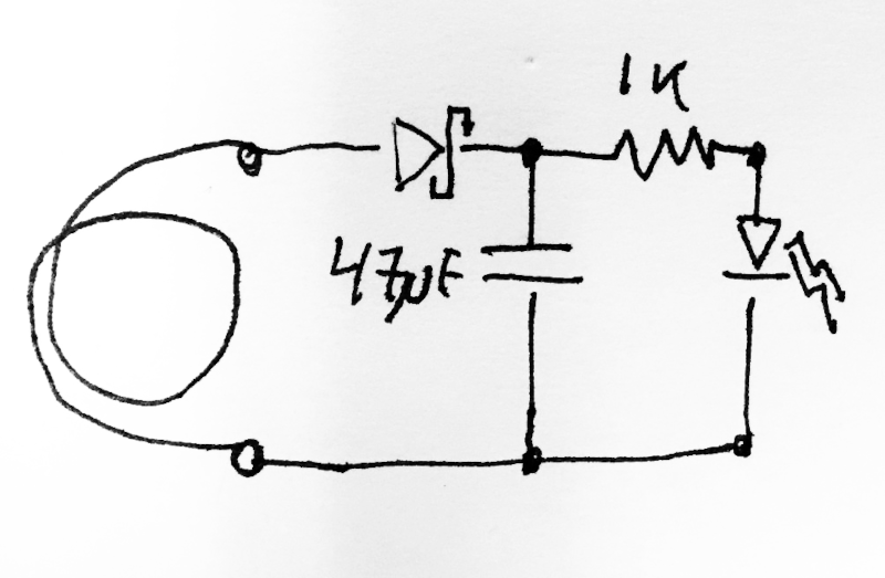
I have made this simple circuit:

enter image description here

Picture of circuit

In response to a rapidly changing magnetic field (pulse), the LED blinks.

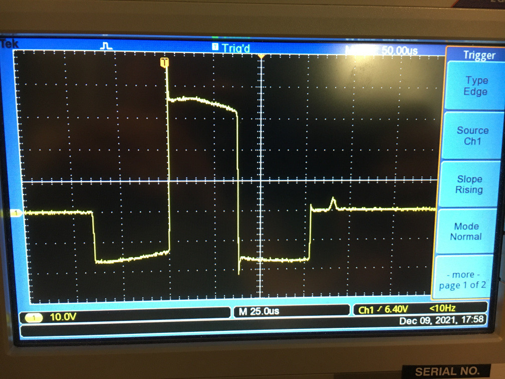
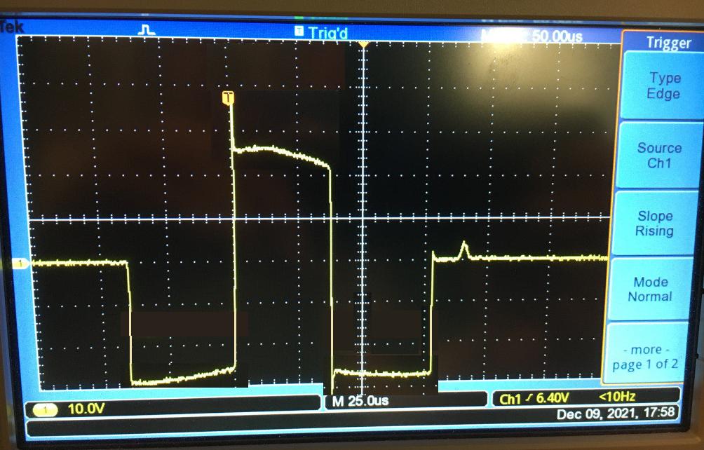
An example of the pulse is shown below:

Picture of scope

Now I would like to have a circuit with 2 LEDs so that only one of the LEDs blinks in response to a pulse like the one shown on the picture above and only the other LED blinks in response to a pulse of the reverse polarity - i.e. as the pulse above, but with the polarity flipped, so it first go positive, then negative and then positive again. The amplitude of the pulses can vary from approx %50 of the shown pulse to 200% of the shown pulse.

Is it possible using only a few more simple components? That is, not adding something like a microcontroller and an external power supply.

\$\endgroup\$
3
  • \$\begingroup\$ The circuit you have will blink the LED in one direction right? So why not simply add the same circuit again but with the connections to the coil swapped so that it responds to the other direction? \$\endgroup\$ Commented Dec 9, 2021 at 10:55
  • \$\begingroup\$ Please note that you might not want to ask if it is possible. Have you tried to add an identical circuit but with opposite polarity? \$\endgroup\$
    – Justme
    Commented Dec 9, 2021 at 10:56
  • \$\begingroup\$ The circuit I have shown above blinks no matter the direction. \$\endgroup\$ Commented Dec 9, 2021 at 11:46

3 Answers 3

2
\$\begingroup\$

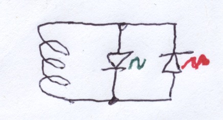
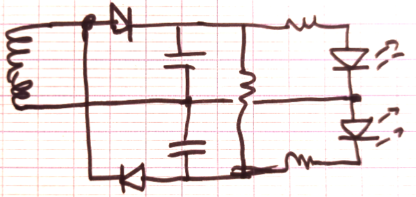
You really only need 2 LEDs connected in inverse parallel. The forward drop of each protects the other from reverse voltage. I have implemented this with a neodymium magnet in closed-end clear plastic tube passing through a relay coil, a solenoid coil with a "U" shaped magnetic path and a permanent-magnet DC commutator motor. Unfortunately none are currently at my location so no photo, just a diagram.

enter image description here

\$\endgroup\$
2
\$\begingroup\$

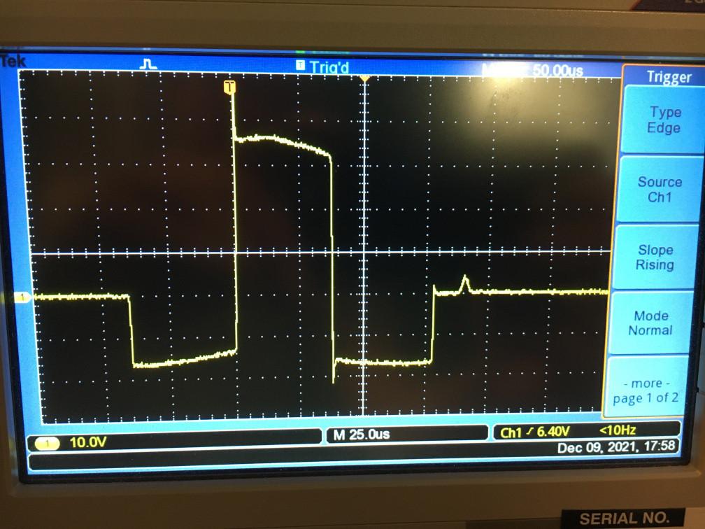
Original diagram of waveform (now changed by OP): -

enter image description here

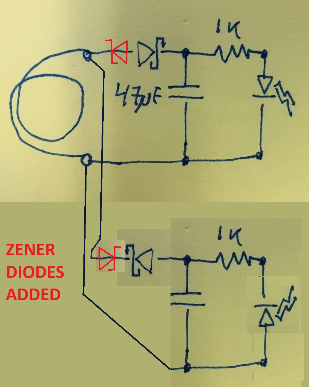
Just parallel up two circuits; one which detects positive and the other detects negative. But add zener diodes so that the voltage needs to overcome a greater threshold to prevent both LEDs flashing on either pulse polarity: -

enter image description here

The zener diode voltages will need to be chosen to be able to block the voltage parts of the waveform you do not want to produce light.


New information coming to light late in the day: -

The amplitude of the pulses can vary from approx. %50 of the shown pulse to 200% of the shown pulse.

Here's how I see your goal-post change: -

enter image description here

I've lowered the positive pulse to 50% and increased the negative pulses by 100%. A simple circuit will not work here based on adding a zener diode to produce a dead-band. As you can see, the positive pulse amplitude can easily be the same as the negative pulse amplitude.

Is it possible using only a few more simple components?

This is the $64,000 question - can you throw a few passives and diodes at this and make it work - maybe, but nothing is springing to mind.

That's my answer and that's an answer to your question.

If you can find a way of detecting the first pulse polarity and subsequently "snubbing" the two following pulses then this might work.

\$\endgroup\$
7
  • \$\begingroup\$ My initial circuit blinks no matter the polarity of the pulse, as the pulse has both a negative part and a positive part. Unfortunately it is not so simple as to just add the circuit you suggest. \$\endgroup\$ Commented Dec 9, 2021 at 11:44
  • \$\begingroup\$ @RasmusFriisKjeldsen how can that be so given you have diodes that protect against reverse polarity? I believe you may be misled. \$\endgroup\$
    – Andy aka
    Commented Dec 9, 2021 at 11:46
  • \$\begingroup\$ If you look at the pulse, it has 2 negative parts and one positive part. My circuit will light up the led on the positive part, and your added circuit will light up the led on the negative part, so as both are present in the pulse, both leds light up. If the polarity of the pulse is reversed, both leds will still light up. \$\endgroup\$ Commented Dec 9, 2021 at 11:53
  • \$\begingroup\$ From your words, that is exactly what I construed you required. I think you need to be a lot clearer about what you want and, importantly, what you don't want to happen. \$\endgroup\$
    – Andy aka
    Commented Dec 9, 2021 at 11:57
  • \$\begingroup\$ Fair enough, I have clarified my question. Thanks for your response! \$\endgroup\$ Commented Dec 9, 2021 at 12:01
0
\$\begingroup\$

enter image description here

This circuit uses a bunch of passives and a brain.

Both caps will charge to different voltages depending on the maximum positive and negative amplitude of your pulse. Now you want to know which side had the highest amplitude: so you wait for a little bit of time, and it'll be the one with the LED that stays on the longest, because its capacitor has charged up to a higher voltage.

In fact, on second thought, the middle resistor (vertical on the schematic) should really have a 3.3V zener in series. So, it will discharge both caps quicker when voltage is higher than 3.3V, which means both LEDs will be on for a shorter amount of time. And it will stop discharging when the sum of voltages on both caps is lower than 3.3V, which is enough to keep only one LED lit, so it will stay lit for longer. Some tinkering will be required. The resistor should probably be a pot.

\$\endgroup\$

Your Answer

By clicking “Post Your Answer”, you agree to our terms of service and acknowledge you have read our privacy policy.

Not the answer you're looking for? Browse other questions tagged or ask your own question.